
NSX Advanced Load Balancer with One-Arm Topology on VMware Cloud on AWS: Design and Deployment Guide
Introduction
VMware's NSX Advanced Load Balancer (NSX ALB) is a versatile solution that offers load balancing, web application firewall, and application analytics capabilities across on-premises data centers and multiple clouds. By leveraging a software-defined platform, NSX ALB ensures that applications are delivered reliably and securely, with consistent performance across bare metal servers, virtual machines, and containers.
Since VMware Cloud on AWS SDDC version 1.9, NSX Advanced Load Balancer has been available as a customer-managed solution. In this setup, the NSX ALB controllers and Service Engines (SE) are manually deployed as VMs through vCenter in a VMware Cloud on AWS SDDC. Several VMware blogs and techzone articles have been released about deploying NSX ALB on VMware Cloud on AWS. For further information, please refer to the following links:
- Build Load Balancing Service in VMC on AWS with NSX ALB
- Deploy and Configure NSX Advanced Load Balancer on VMC on AWS
NSX ALB offers two main topologies for load balancing: one-arm and inline topology. This guide provides an overview of deployment consideration and best practices for deploying a one-arm topology NSX ALB on VMware Cloud on AWS. For deploying NSX ALB inline topology on VMware Cloud on AWS, please refer to https://vmc.techzone.vmware.com/resource/designlet-deploy-nsx-advanced-load-balancer-inline-topology-vmc-aws
Summary and Considerations
| Use cases | Provide application load balancing service on VMware Cloud on AWS |
| Pre-requisites | Understand single-AZ and multi-AZ VMware Cloud on AWS SDDC network architecture, vSphere compute policy, NSX ALB HA modes and deployment topologies: one-arm topology and inline topology. |
| General consideration | The one-arm topology is generally preferred for several reasons:
When deploying the one-arm topology, it's important to consider the following recommendations and best practices:
|
| Performance Considerations |
|
| Cost Implications | When provisioning additional SEs to accommodate for failure, extra costs (license and computing resources) for these buffer SEs are required. |
| Documentation Reference | Designlet: Understanding VMware Cloud on AWS Network Performance |
| Last Updated | May 2023 |
Planning and Implementation
The following sections provide the details for planning and implementing an NSX ALB one-arm topology deployment.
NSX ALB Controller Cluster
it's recommended to place the NSX ALB controller in a network segment connected to a routed T1 or the default compute gateway (CGW) to simplify the connectivity configuration of the deployment.
It is recommended to allocate a separate routed network segment specifically for the NSX ALB Controller and SEs' management interface. This approach will minimise any potential interruption for SEs’ control plane communication.
The network latency requirement between controllers (< 10ms) and between controllers and SEs (< 70ms) is typically not a concern in a VMware Cloud on AWS SDDC, including in a multi-AZ AWS SDDC. This is because the AWS cross-AZ latency is generally within 10ms.
In multi-AZ VMware Cloud on AWS SDDCs, it's common practice to deploy all controllers in the same AZ. This approach ensures the minimum latency between them. Spreading them across both AZs doesn't improve the system's availability in a meaningful way, as the SEs can continue to process requests if the controller cluster is down.
NSX ALB Cloud Type
NSX ALB provides out-of-the-box integrations for on-premises or cloud deployments. These integrations with private cloud frameworks, software-defined network (SDN) controllers, container orchestration platforms, virtualized environments and public clouds enable turnkey application services and automation.
At the time of writing, No-Orchestrator is the only supported NSX ALB cloud type configuration for VMware Cloud on AWS SDDC. There is no integration between NSX ALB and the underlying infrastructure in the No-Orchestrator cloud, and SEs are not automatically deployed and configured through the NSX ALB control plane.
NSX ALB SE Group
The supported high-availability (HA) mode for one-arm SEs includes the following:
- Elastic HA Active/Active mode: In active/active mode, NSX ALB places each virtual service on more than one SE, as specified by “Minimum Scale per Virtual Service” parameter— the default minimum is 2. If an SE in the group fails, then Virtual services that had been running are not interrupted. They continue to run on other SEs with degraded capacity until they can be placed once again.
- Elastic HA N+M Mode: N+M is the default mode for elastic HA. The “N” in “N+M” is the minimum number of SEs required to place virtual services in the SE group. The “M” of “N+M” is the number of additional SEs spun up to handle up to M SE failures without reducing the capacity of the SE group. M appears in the Buffer Service Engines field in the SE group settings. In this mode, each virtual service is typically placed on just one SE.
- Legacy HA mode: In legacy HA mode, exactly two NSX ALB SEs are configured in a SE group. By default, active virtual services are compacted onto one SE; the other SE in the pair is the standby for that virtual service, carrying no traffic while the other SE is healthy. Upon failure of an SE, the surviving SE takes over traffic for all virtual services previously active on the failed SE, while continuing to handle traffic for virtual services already assigned to it. Legacy active/standby is useful for migrating from hardware appliance-based solutions to NSX ALB.
VMware generally does not recommend Legacy HA due to its lack of scale-out capability. In elastic HA active/active mode, application performance may be affected in the event of a host failure. This is because it takes time for the affected SE to return online or for a replacement SE to be deployed, especially considering that SE LCM (Life Cycle Management) is not supported in NSX ALB No-Orchestrator mode, which can further prolong the impact on performance. To ensure consistent application performance, it is recommended to use elastic HA Active/Active mode with additional capacity. For example, if the application requires 2 SEs for the planned regular workload load balancing traffic, we can provision an additional SE and scaleout the VS to 3 SEs to accommodate the host failures/SE failures without impacting the application performance.
Each SE within a one-arm SE group can connect its data vNICs to one or multiple NSX T1 routers. When using multiple data vNICs, a separate NSX ALB VRF context is required for each T1 connection. The T1 routers will serve as the default gateway for each VRF context.
Commonly Used Topologies
In this section, several common one-arm topologies on VMware Cloud on AWS will be discussed, As NSX ALB controllers and SEs’ management interfaces are recommended in the same network segment, the topology diagrams don’t include SE’s management connectivity for simplicity.
By default, only a single default T1 router CGW is deployed providing connectivity for customers’ workloads in a VMware Cloud on AWS SDDC. In this single T1 SDDC, the following NSX ALB one-arm topologies are often seen.
- Single AZ SDDC NSX ALB One-Arm Topology: Shared SE Group Across Security Zones
As shown in Figure 1, the data interfaces of the SEs connect directly to the CGW. The SEs access the backend servers of the NSX ALB virtual service through the CGW. The same SE group serves all backend network segments. SEs have one or multiple (up to 9) data interfaces connected to the CGW, and each interface is placed into a different NSX ALB VRF context. VIPs for security zone 1 will be allocated from network segment 1, and VIPs for security zone 2 will be allocated from network segment 2. This basic and simple setup is suitable for a customer who does not require security separation at the SE group level for different backend security zones or domains.
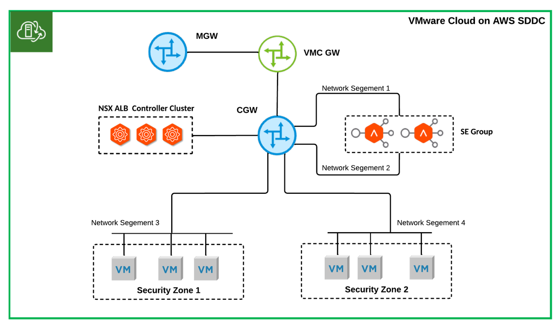
Figure 1 Single AZ SDDC NSX ALB One-Arm Topology: Shares SE Group Across Security Zones
- Single T1 SDDC NSX ALB One-Arm Topology: Dedicated SE Group Per Security Zone
Different SE groups are possibly necessary for different security zones in a highly regulated environment. For instance, a dedicated SE group might be required for DMZ applications. Figure 2 illustrates a topology that fulfils these requirements.
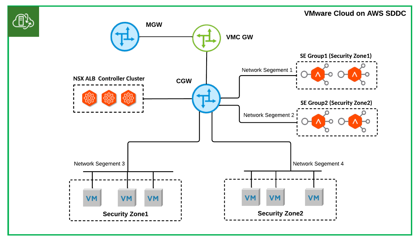
Figure 2 Single-T1 SDDC NSX ALB One-Arm Topology: Dedicated SE Group Per Security Zone
- Single T1 SDDC NSX ALB One-Arm Topology: On-prem Migration
As shown in Figure 3, the data interfaces of SEs within a SE group stay in the same network segments as the backend servers they are serving. The VIP will be allocated from the same IP ranges as the backend servers. This topology mostly results from migrating existing on-prem physical load-balancing deployments to the cloud without optimisation. The performance gain of bypassing layer three routing by use of this topology during load balancing is insignificant in a virtualised, distributed software-defined networking environment like VMware NSX-T. As backend servers and VIP share the same IP range, it makes IP management more complicated. Moreover, the number of network segments served by each SE group in this topology is limited to 9 because each SE appliance can only have up to 9 data vNICs, making it unsuitable for a large deployment.
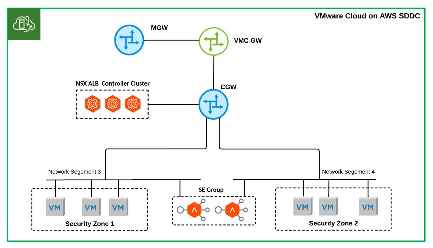
Figure 3 Single T1 SDDC NSX-ALN One-Arm Topology: On-prem Migration
In a multi-T1 VMware Cloud on AWS SDDC, additional T1 routers are typically deployed to support multiple tenants. The following are two widely used topologies.
- Multi-T1 SDDC NSX ALB One-Arm Topology: Shared SE Group
Figure 4 illustrates a topology in which a single SE group is used to serve different tenants, where security separation at NSX ALB VRF Context level is considered sufficient. For tenant 1, VIPs are allocated from network segment 1, while for tenant 2, VIPs are allocated from network segment 2.
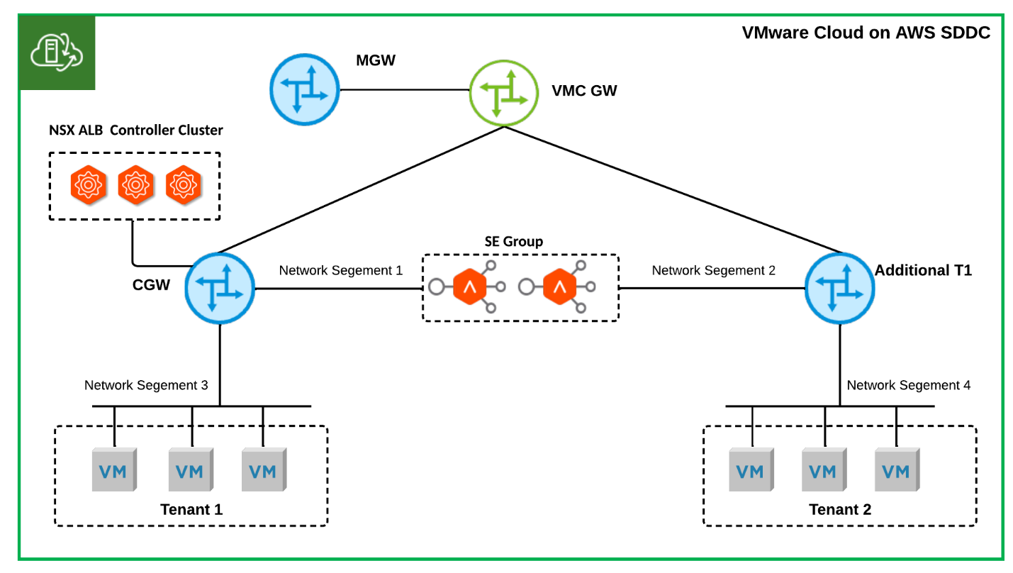
Figure 4 Multi-T1 SDDC NSX ALB One-Arm Topology
- Multi-T1 SDDC NSX ALB One-Arm Topology: Dedicated SE Group Per Tenant
Figure 5 illustrates a topology where each tenant/T1 router has a dedicated SE group. This topology is particularly suitable for customers such as Load Balancing Service Providers who require a dedicated SE group for each tenant. In this configuration, NSX ALB control plane separation between tenants can be achieved by creating a NSX ALB tenant for each customer and enabling Tenant Context Mode.
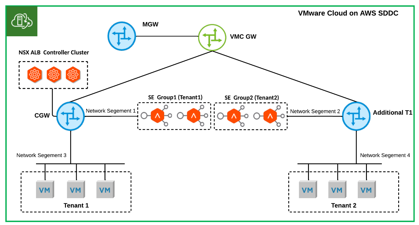
Figure 5 Multi-T1 SDDC NSX ALB One-Arm Topology: Dedicated SE Group Per Tenant
Virtual IP (VIP) Allocation
NSX ALB Load-balancing VIPs can be manually allocated or done via NSX ALB IPAM or supported 3rd party IPAMs.
As only the No-Orchestrator cloud is supported by NSX ALB on VMware Cloud on AWS, in the one-arm topology, VIP can generally only be assigned from the available IPs in the SEs' data interface subnet. Therefore, it's crucial to properly size the subnets for these network segments at the beginning of the deployment to ensure sufficient IP resources for VIP allocation. Because VIPs and SE data interfaces use the same IP subnet, it is recommended to use separate ranges for them. For instance, in a /24 subnet, reserve the first 32 IP addresses for SEs' data interface IP and allocate the remaining IP addresses for VIPs. This approach promotes organized IP allocations and simplify firewall rules configuration.
Distributed Firewall (DFW)
In a one-arm topology with the No-Orchestrator mode, each NSX ALB virtual service is served by multiple SEs simultaneously when running in elastic HA active/active or elastic HA N+M mode when N>1. One of the SEs works as the primary SE for the virtual service, and the rest of the SEs works as the secondary SEs. All traffic from clients to a virtual service will always go to the primary SE, and the primary SE will forward a percentage of inbound client traffic to the secondary SEs. The secondary SEs will source NAT the traffic from its own IP address when load balancing the flow to the backend application servers. Servers will respond back to the source IP of the connection (the secondary SEs), ensuring a symmetrical return path from the server to the SE that owns the connection. With the default settings, the secondary SEs will send the return traffic to the client directly, bypassing the primary SEs. Figure 6 shows the end-to-end data flows.
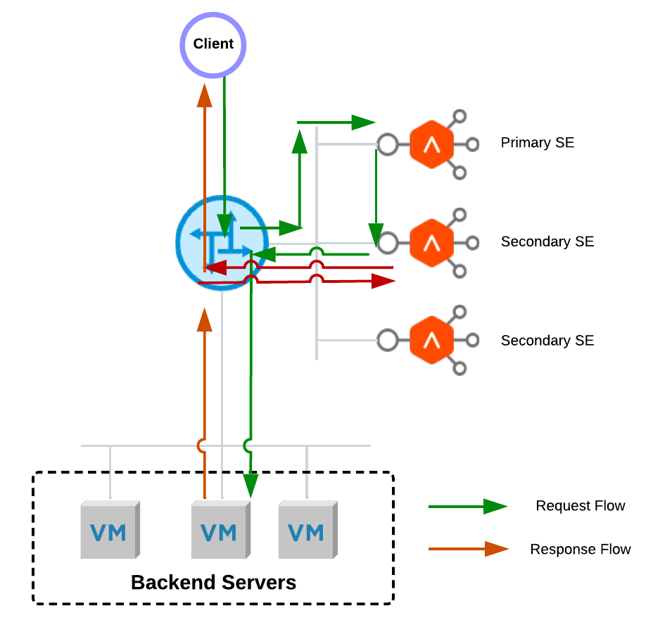
Figure 6 NSX ALB Default Elastic HA Data Flow
Due to the asymmetric data flow path, NSX-T DFW will drop sessions on the secondary SEs.
Adding SEs to the DFW exclusion list is not desired, especially in a highly regulated environment. To make NSX-T DFW work well together in elastic HA active/active or N+M mode, there are two options available:
- Remove Asymmetric Data Flow Path
Enabling tunnel mode between the primary SE and secondary SEs removes the asymmetric path by forcing all return traffic from backend servers to the primary SE from the secondary SE before sending it back to the client. Consequently, because all return traffic will go through the primary SE, the primary SE can be a performance bottleneck in high-load environments. Please note that the tunnel mode setting won't take effect until the SE is rebooted because this is a global change.
- Configure DFW to Accommodate Asymmetric Data Flow Paths
In order to allow for asymmetric data flow paths, you can disable TCP Strict checking in the DFW policy. To limit the impact of this change, it's recommended to create a dedicated DFW policy for communication between clients and SEs and between SEs only. Make sure to disable TCP Strict checking only for this policy. For further information about NSX-T DFW policy TCP Strict, please refer to Add a Distributed Firewall.
The choice between these two options should be based on the security requirements and the specific environment.
SE Performance
CPU and memory reservation is a crucial technique administrators can use to ensure optimal SE performance. As performance requirements increase, CPU and memory reservations can be applied to the SEs to provide them with guaranteed resources from the underlying host. Reservations can be increased all the way to 100% to provide the most consistent performance.
In addition to CPU and memory reservation, adopting newer hardware, such as the i4i node, can provide better performance and reliability for SEs. Newer hardware often comes with advanced features and specifications that can enhance the performance of SEs, providing better response times, throughput, and reliability.
VMware Cloud on AWS provides several storage options, including full flash vSAN, AWS FSx for NetApp ONTAP, and Flex storage. Among these, vSAN with a RAID1 (with Dual-Site mirroring for a multi-AZ VMware Cloud on AWS SDDC) storage policy is recommended for deploying Service Engines as it provides the best write performance, which is required for collecting real-time metrics for virtual services.
Service Resilience
To minimize service interruptions in the event of VMware Cloud on AWS host failures, it is highly recommended to apply VM-VM Anti-Affinity compute policies to NSX ALB controllers and SEs in a group. This policy ensures that a single host failure does not impact more than one NSX ALB controller or multiple SEs in a single SE group.
When load balancing an application distributed across two AZs in a multi-AZ VMware Cloud on AWS SDDC, it is recommended to apply VM-Host affinity compute policies to distribute the SEs across different AZs. This ensures that at least one SE is available in case of an AZ failure, minimizing interruptions to the load balancing service and connectivity.
To understand the resilience of applications served by NSX ALB, it is important to be aware of different failure scenarios in Elastic HA Active/Active mode or Elastic HA N+M mode:
- As shown in Figure 7, in the event of a host failure, the NSX control plane service will continue running, but the primary SE for a virtual service may be affected. An operational SE will assume the role of primary SE and send gratuitous ARPs for the VIP of the virtual service. The new primary SE will continue the load balancing service. The service recovery time is typically from 10 to 15 seconds.
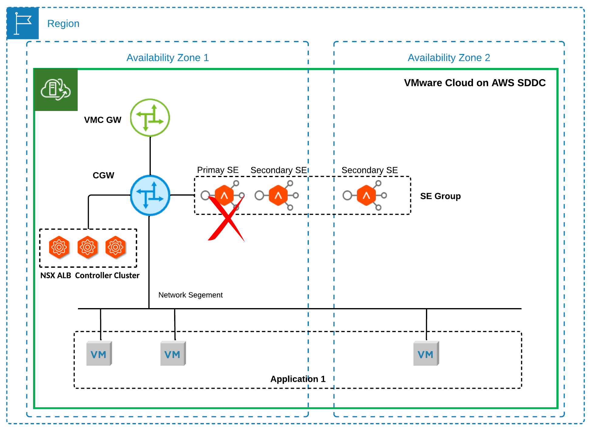
Figure 7 Failure Scenario 1
- As shown in Figure 8, in a multi-AZ SDDC, if an AZ failure occurs and causes both the NSX ALB control plane service and the primary SE for a virtual service to go down, a secondary SE for that virtual service in the operational AZ can quickly become the primary SE using the Service Engine Self-Election feature in the SE group. This allows it to take over without waiting for the NSX ALB control plane service and the original primary SE to recover. By modifying the default setting of 'controller_heartbeat_timeout_sec' to 5 seconds, the service recovery time can be reduced to approximately 30 to 40 seconds. VMware does not recommend changing the timeout setting to a value lower than 5 seconds for VMware Cloud on AWS customers as it may result in unnecessary failovers.

Figure 8 Failure Scenario 2
- As shown in Figure 9, In a multi-AZ SDDC, if an AZ failure occurs, resulting in the NSX ALB control plane service going down while the primary SE for a virtual service remains operational in another AZ, the primary SE will continue forwarding traffic in a headless mode. This means that clients can still access the virtual service.
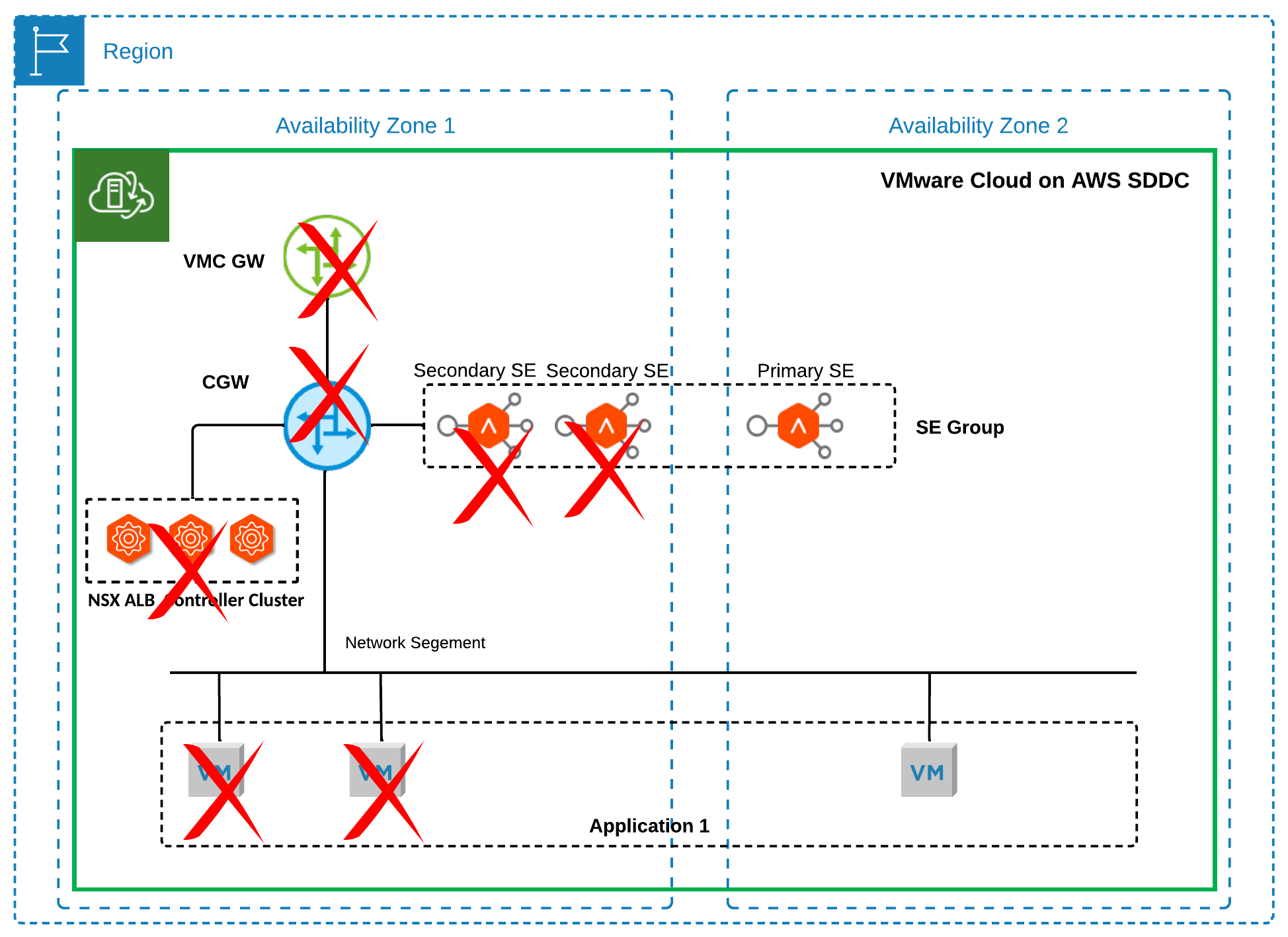
Figure 9 Failure Scenario 3
- As shown in Figure 10, in a multi-AZ SDDC, if an AZ failure causes the primary SE for a virtual service to undergo vSphere HA reboot while the NSX ALB control plane service remains unaffected, one of the remaining operational SEs will assume the role of the primary SE. The new primary SE will send gratuitous ARPs for the VIP of the virtual service and continue serving the load balancing service. Service recovery time typically ranges from 10 to 15 seconds.
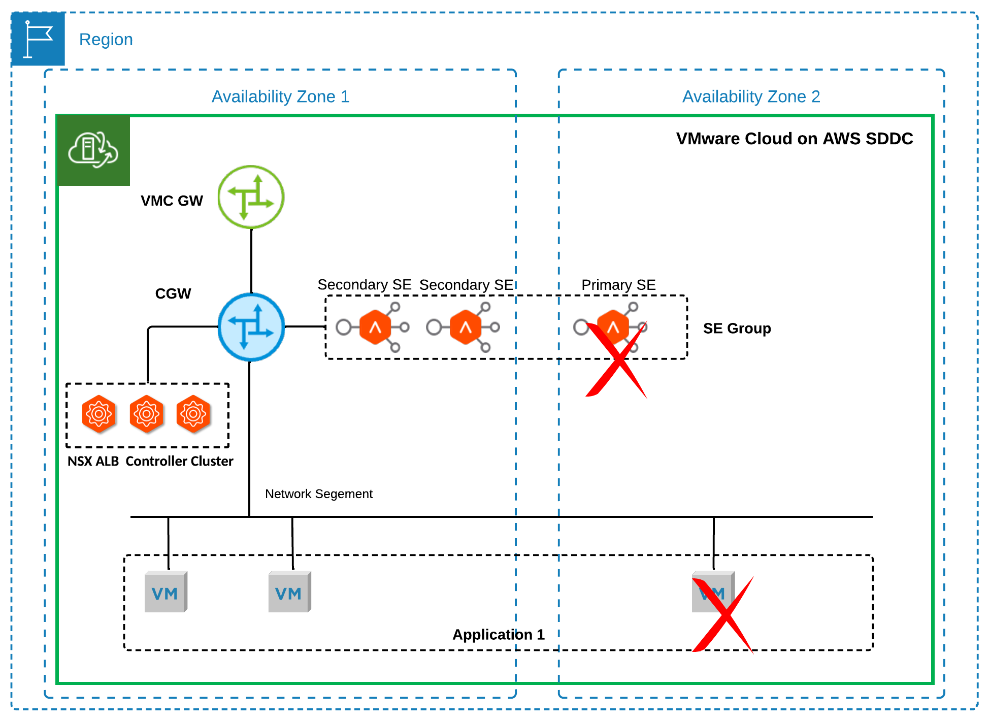
Figure 10 Failure Scenario 4
- As shown in Figure 11, in a multi-AZ SDDC, if an AZ failure occurs, it only affects the secondary SEs for a virtual service, while both the NSX ALB control plane service and the primary SE for that virtual service remain operational. The primary SE will continue forwarding traffic, allowing clients to access the virtual service.
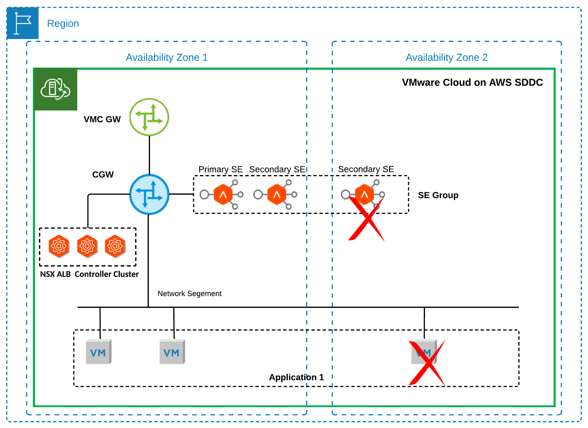
Figure 11 Failure Scenario 5
Please note that application performance will degrade until the impacted SE comes back online if no buffer SEs are available during the above failure scenarios.
In Legacy HA mode, if an AZ failure causes the NSX ALB control plane service to go down while the active SE remains unaffected, the load balancing service will continue forwarding traffic for the configured virtual services. If the active SE for these virtual services is also impacted, the standby SE in the operational AZ will become active to provide load balancing services once the NSX ALB control plane service is restored.
It's important to note that if the NSX Edge appliances are affected by an AZ failure, end-to-end connectivity for north-south load balancing will not be restored until the NSX Edge appliances are back online.
Service Monitoring
NSX ALB service monitoring is required for NSX ALB controllers, SEs and relevant components such as NSX Edge appliances and physical ESXi hosts on which SEs run. In cloud environments like VMware Cloud on AWS, limitations are more commonly based on packets-per-second (PPS), closely monitoring this metric for NSX Edge appliances and physical ESXi hosts’ elastic network adapters in high-load environments is recommended. This will help to ensure that the NSX Edge and ESXi hosts are not overwhelmed by traffic and that optimal performance is maintained. For further information about VMware Cloud on AWS network performance, please check Designlet: Understanding VMware Cloud on AWS Network Performance.