
Deploy and Configure NSX Advanced Load Balancer on VMC on AWS
Introduction
An introduction to the NSX ALB Architecture, its components, and a few use cases is discussed in the Introduction to NSX ALB article.
Scope
The purpose of this document is to walk you through the steps of deploying & configuring NSX ALB in an SDDC running in VMware Cloud on AWS.
Note: Currently, NSX ALB is not offered as a SaaS service in VMware Cloud on AWS and is completely a customer-managed solution.
Note: All references to Service Engine or service engine refer to NSX ALB Service Engine.
Summary and Considerations
The following table lists the use cases and deployment considerations for NSX ALB implementation in VMware Cloud on AWS.
|
Pre-requisites |
|
|
General Considerations/Recommendations |
|
|
Cost Implications |
If Public IPs for NSX ALB are used, then it incurs charges. To know more about the charges, please see VMC on AWS Pricing Guide. |
|
Performance Considerations |
Service Engines are shared among virtual services, CPU/Memory reservations can be configured on the service engine vm's for guaranteed performance. |
|
Documentation reference |
Deployment Requirements
|
Hardware Requirements |
Note: For guaranteed performance, customers can specify CPU & Memory reservations on the NSX ALB Controller and Service Engine VMs. By default, no reservations are configured. |
||||||||||||
|
Network Requirements |
3 logical segments backed by distinct subnet. These must be pre-provisioned before NSX ALB deployment in VMC.
The purpose of these subnets are explained below:
|
||||||||||||
|
Port & Protocols Requirement |
Note: Port 22 is used for communication between Avi components for configuration sync, metrics and logs transfer, heartbeats, and other management processes. |
Deployment Considerations
The easiest way to deploy NSX ALB Controller in VMware Cloud on AWS is to create a local Content Library and import the NSX ALB Controller as an ova template.
Invoke the create a new virtual machine wizard and deploy using the NSX ALB Controller ova template from the content library.
Once the controller VM is deployed and boots up, perform the initial configuration by connecting to URL https://<avi-controller01-fqdn>/
Configure the following parameters:
- Admin user credentials and email address.
- DNS server to be used for name resolution and backup passphrase.
- (Optional) configure SMTP settings for the controller VM to send alerts to an email in case of any issues with NSX ALB.
- Choose No Orchestrator mode when configuring Avi Controllers in VMware Cloud on AWS.
Image

- Select multi-tenancy if you want it. Here, multi-tenancy is set to No.
- After the initial configuration is completed, you are taken to the NSX ALB Controller dashboard page. Continue and complete the rest of the configuration.
- The first controller of the cluster receives the "Leader" role. The second and third controllers will work as "Follower".
- Log into the GUI and navigate to Administration > Controller to verify the controller role.

Configure NSX ALB Controller Cluster
For high availability, a minimum of 3 controller nodes is required to form a highly available cluster. Repeat Steps 1-5 for deploying & configuring additional Controller VMs.
To configure the controller cluster, navigate to Administration > Controller and click on the pencil icon to edit the controller settings.
Provide a name for the Controller cluster and specify the controller cluster IP. Enter the IP information for each node. An example screenshot is shown below.

It takes approximately 5-7 minutes for cluster formation to complete. You will be automatically logged out of the controller node where you are currently logged in. On entering the cluster IP in the browser, you can see details about the cluster formation task.

Once the cluster formation is completed, you can login to the controller via the cluster IP and can verify the state and role of the controller nodes.

Deploy and Configure Service Engine
Deployment of service engine is manual in VMC on AWS because the cloudadmin@vmc.local user does not have all required permissions to read/write to vCenter API and there is no access to the ESX management plane. Access to the ESX management plane is required for Service Engine automated deployment in VMC on AWS vCenter instance.
Create and Download Service Engine Image
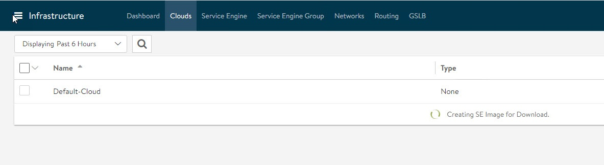
To download the Service Engine image for deployment, login to the NSX ALB controller via admin user and navigate to Infrastructure > Cloud. Select the default cloud and click on the download icon and select type as ova.

Wait for a couple of minutes for the image generation task to complete. The ova image file is automatically downloaded when the task completes.
Import Service Engine image file into the content library
The downloaded ova file can be used directly to create a Service Engine VM, but this requires uploading the image to vCenter every time a new SE VM needs to be created. For faster deployment, import the SE ova image in the content library and use the "deploy from template" wizard to create new SE VMs.

Generate Cluster UUID and Authentication Token
Before deploying Service Engine VMs, you need to get the cluster UUID and generate authentication token. Cluster UUID facilitates Service Engine Integration with NSX ALB Controller and authentication between the two is performed via authentication token.
To generate Cluster UUID and auth token, navigate to Infrastructure > Clouds and click on the key icon against default cloud. A new pop window will open and it contains both Cluster UUID and auth token. You need a new auth token every time a new service engine instance is deployed.

Deploy Service Engine VM
Log in to the vSphere client and navigate to Menu > Content Library. Select Templates and click on the New VM from this template to create a new VM as shown below.

Follow the VM creation wizard and on the networks page, select the management and data networks for the SE VM.
The Management network label (vNIC0) is mapped to the management logical network. The remaining network labels (Data Network 1 – 9) are connected to any of the front-end virtual service’s network or back-end server’s logical network as required. It is left disconnected if not required.

On the Customize template page, provide the Controller IP address details, the Cluster UUID, and the authentication token generated earlier.

Review the settings and click Finish to initiate Service Engine VM deployment. Power on the VM post-deployment.
Repeat the steps to deploy additional Service Engine VMs. Once all SE VMs are powered on, SE automatically registers themselves with the NSX ALB Controller.
Log in to the Controller and navigate to Infrastructure > Service Engine to verify the Service Engine integration status. For a successful deployment of Service Engine, note the Health score and the status. The health score buildup takes some time to show the final number. The status should be UP, and ideally, the health score should be 100.

At this point, Service Engine has established the control and management plane communication with the NSX ALB Controller.
Configure Default Gateway for Service Engine Data Network
The next step is to add a default gateway for the SE Data network. To do so, navigate to the Infrastructure > Routing > Static Route page and add a default static route as shown below.

Configure Service Engine Data Network IP Address
If static IPs are used on the segment selected for NSX ALB data communication, then the Service Engine needs to be modified and the IP address to be configured manually. To do so, first, obtain the Mac address of the Service Engine VM data network.

Navigate to the Service Engine page in NSX ALB Controller UI and click the Pencil icon to edit the Service Engine settings.

Locate the Mac Address that you noted down earlier and configure the IP address corresponding to the data network.
NSX ALB deployment and configuration is now completed. You are now ready to leverage NSX ALB for load balancing applications.