
VCDR Components and Inventory and Resource Mapping
VMware Cloud Disaster Recovery Components
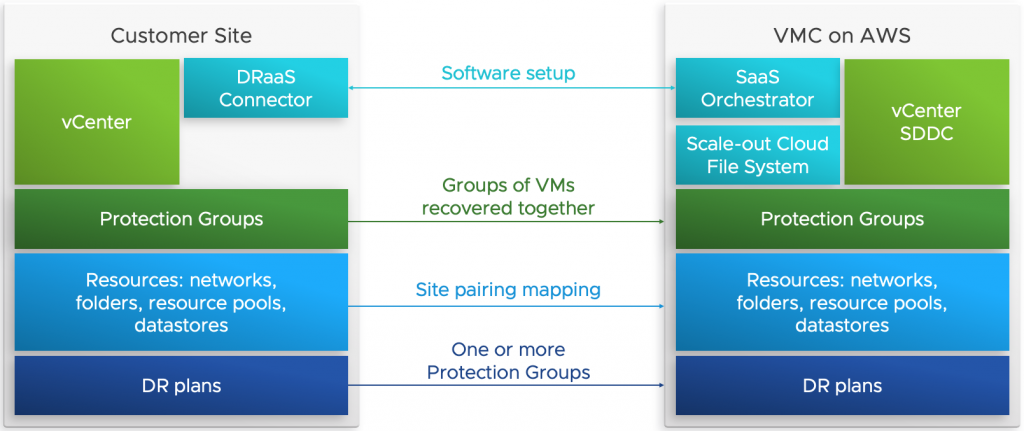
VCDR solution has 3 main components that make up the overall architecture. They are:
- Protected Sites - and the policies that provide the coverage of your production workloads whether they are in on-premises data center locations or running in other VMC SDDCs
- Scale-out Cloud File System (SCFS) - that provides the immutable, off-site recovery points for effecting the desired site failover, managed by a separate Orchestrator UI running as a service in VMware Cloud
- VMC Recovery SDDC - the DR site in the cloud - for running workloads when the Protected Site has experienced a disaster
Protection Group
Grouping a set of VMs which can be then be used during recovery is facilitated from the protection group. You can create many such groups. VMs that are a part of a protection group should exist on the same protected site only. To create a protection group, you must have a an existing subscription.
A protection group consists of the following components:
- Site selection (on-premises or SDDC vCenter)
- Members (VMs)
- Policies for snapshots (schedule, retention)
- Cloud backup site (SCFS)
Note : The members of a single protection group must share the same vCenter. In other words, you cannot create a protection group that contains VMs from two different vCenters.
Disaster Recovery Plan
A DR plan defines the orchestration configuration for disaster recovery and workload mobility.
You can create, name, edit, duplicate, save, and run DR Plans. Environment variables in a plan map differences between the sites for smooth recovery, ensuring that vSphere configurations and parameters are mapped consistently between sites.
Plans run either for recovery as an actual DR operation, or they run as a test recovery, which perform all the plan’s recovery operations in a test site for validation.
VMware Cloud Disaster Recovery can maintain multiple plans of different types, and the plans can be in various stages of execution at any given time, even concurrently.
Operation allowed under the DR plan section are:
- Configure DR Plans - require defining where you want your protected data moved to when the plan runs.
- View DR Plans - shows the currently defined plans along with plan summary information: the current status, protected and recovery sites, and the last run compliance check results.
- Activate DR Plans - can be in an active or deactivated state.
Failover
A DR plan includes a set of recovery steps that capture ordering constraints and action sequencing instructions for DR operations, which occur when you run the plan.
You can run a DR Plan either as a failover or a Test Failover. The running plan creates a ‘workflow instance’ - a runtime representation of the recovery steps in the plan, combined with other information available only when the plan starts running, such as the snapshot selection coupled with the plan's underlying failover operations.
Plan recovery steps apply to the plan itself and control the failover workflow. For example, a planned failover creates a workflow of operations based on the recovery steps defined in the plan. An executing plan’s recovery steps are run on the source site (power off VMs, replicate the last snapshot) and destination site (recover VMs in the predefined order).
An unplanned failover creates a different workflow based on the same recovery steps defined in the plan.
Note the following:
- If the test site is deactivated, the test tab is not displayed.
- If the test site is specified, the Failover mappings and Test mappings tabs can be the same depending on check box selection.
Failback
You can run a DR Plan to failback from a VMware Cloud on AWS SDDC to a protected vSphere site. Failback from an SDDC returns only changed data. There is no rehydration, and the data remains in its native compressed and deduplicated form. You can run the failback plan by clicking the Failover from VMC button.
A failback from VMware Cloud on AWS runs a number of steps, including the following:
- VMs are powered off on the SDDC.
- The last VM snapshot is taken following the power off. The differences between the VM state at the time of recovery and failback are then applied to the snapshot used for recovery to construct a VM backup on the SCFS for subsequent retrieval.
- These VM backups are then retrieved to an on-premises system using a general forever incremental protocol.
- VMs are recovered to a protected vSphere site.
- Upon successful recovery, VMs are automatically deleted from the SDDC.
Once a failback DR plan is created from duplicating the plan and reversing its steps, the new failback plan operates the same way as any other plan. You can edit the plan to change the destination site to point to a new VMware Cloud Disaster Recovery protected site. Or, you can change the vCenter mapping if the failback target site has more than one protected site.
You can also use a new protected site and/or vCenter for failback, if the proper mappings are configured, but in this case incremental recovery is possible. If VMware Cloud Disaster Recovery can find a VM with the same instance UUID, then an incremental recovery is performed. If VMware Cloud Disaster Recovery cannot find the same instance UUID for a VM, then a full recovery is initiated.
Restore a VM
Once a protection group has taken snapshots of the VMs on your protected site, you can restore individual VMs from a snapshot back to the protected site.
The VM will be restored to the same state it was in when the snapshot was taken, including its vCenter location, configuration, data, etc.
You may need to restore a VM during a failed software upgrade attempt or when something was accidentally deleted or uninstalled from a virtual machine.
Inventory and Resource Mapping
The following image shows the list of resources/inventory that can be mapped between the protected and recovery sites for a particular DR plan.
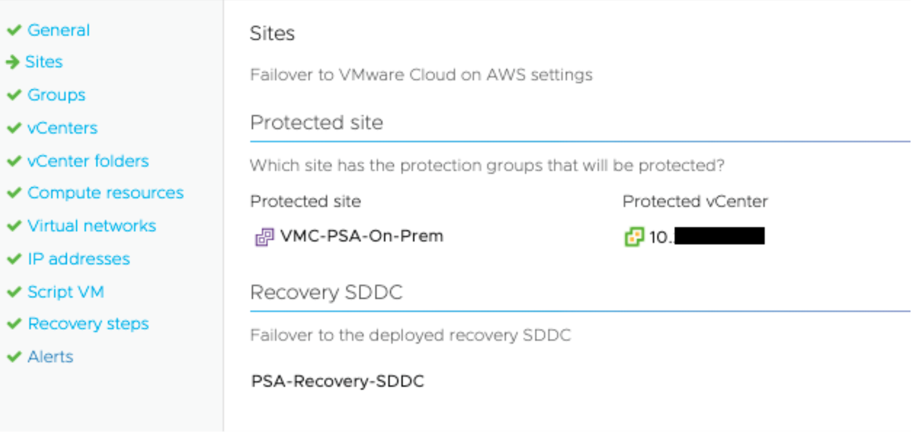
vCenter Mapping
Mapping vCenters in a DR plan consists of selecting source vCenters that are registered to the protected site. Choosing a target vCenter for a Failover SDDC is simple; each SDDC contains a single vCenter instance. For VMware Cloud Disaster Recovery, keep in mind that a protected site can have multiple registered vCenters, but you can only map one vCenter on VMware Cloud on AWS per-DR plan.
Every valid vCenter mapping will create a vCenter mapping for the following three elements:
- vCenter folders
- Compute resources
- Virtual networks
Resource Pool and Folder Mapping
This page of the plan wizard displays a subset of the vCenter object inventory for both the source and target vCenters. Source vCenter object nodes that are detected to contain protected VMs are required to be mapped and are displayed in the UI with blue text. All other mappings are optional.
Add a Mapping
- Select the source vCenter node and the corresponding target vCenter node indicating where the source VMs should be recovered.
- Click Add.
- Complete this step for each mapping.
- Click OK when finished.
Note: If your VMs on the protected vSphere site have tags associated with them, make sure that the same sets of tags and tag categories also exist on the target site of the plan (the Recovery SDDC).
Tip: Avoid having other VMs in target folders because name conflicts can arise when registering VMs with vCenter.
vCenter Folders
Mappable vCenter objects:
- Datacenter
- Folder
Compute Resources
Mappable vCenter objects:
- Clusters. If the Cluster contains VMs, its icon is highlighted in light blue font to indicate that mapping for this item is required(This color scheme applies to all mappings).
- Resource pool
- Standalone host (not in a cluster). Note that a standalone host can only be mapped to another standalone host.
Note: Regarding vCenter cluster names, "Cluster-1-<clusterIndex>" represents the name of the initial cluster when the SDDC was first created.
If the SDDC that your clusters belong to is deleted, then any plans with mappings to clusters on that SDDC will display the target cluster names with an asterisk. For example: "Cluster-*-<clusterIndex>".
Additionally, plan compliance reports will indicate an error when clusters are mapped to a deleted SDDC, or if there is a mapping to a deleted cluster.
Virtual Networks
Mappable vCenter objects:
- Virtual network
- Distributed virtual port group
Datastore Mapping
When performing a failover from VMware Cloud on AWS, datastore mappings are established automatically. The VMware cloud recovery site has a single datastore making datastore mappings unnecessary.
Note: All VMs that are recovered are located at the root storage folder of the "WorkloadDatastore/" directory after the failover operation.
However when a DR plan for failback is created (failback from/to on-onprem), you must configure datastore mapping.
IP address Mapping
IP mappings determine how a VM’s IP address is assigned when a protected source site is failed over to a target site. When a VM is recovered from one site to another, VMware Cloud Disaster Recovery needs to know which IP addresses will be used for the recovered VMs.
IP address mappings can be configured for VMs installed with Linux or Windows guest OS’s. VMs configured for IP address mapping will display with a target IP, target subnet mask, target gateways, and target DNS servers.
Important: In order to map IP addresses for Windows VMs, the system drive of the VMs must be mapped to c:\. Additionally, the mapped c:\ drive cannot be dynamic volume; it must be a basic disk.
Note: VMware Tools must be installed on the guest OS in order to ensure successful IP address mapping. Only iPv4 is supported for protection plan IP address mapping. This means that any VMs referenced in a DR plan must be using iPv4, or the IP address mapping will not work.
Individual IP Address Mapping
The following options are available on IP address mapping page:
- Optional rule description
- Source and target IP addresses
- Source and target subnet masks
- Source and target gateways
- Source and target DNS servers
Entries for gateways and DNS servers must be separated by white spaces. If multiple IP addresses are specified, they will be matched in the specified order from source to target.
IP Address Range Mapping
Alternatively, you can configure IP address ranges rather than individual IP addresses. Switching to IP ranges can be done by selecting Range from Range/IP addresses, as shown below:
Limitations when mapping IP address ranges:
- You can provide a bits value that is smaller than the subnet mask size (CIDR prefix). For instance, if the subnet is a /20 you can define a CIDR prefix (bits) that provides a smaller IP range (i.e., /21, /22, etc.) for the range mapping.
- You cannot, however, do the reverse. If the subnet is a /20 you cannot enter a CIDR prefix (bits) that provides a greater IP range (i.e., /19, /18, etc.) for the range mapping. If attempted, the UI will display an error.
Reports
VMware Cloud Disaster Recovery provides report generation in the PDF format for failover and test failover operations, plan configuration changes, and compliance checks.
Configuration Reports
The generated report contains a summary of the plan configuration, failover mapping details, and the configured failover steps
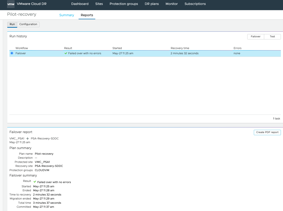
Failover and Test Failover Reports
Failover and test failover reports provide information about a completed DR plan operation.
After a failover or test failover plan has completed (and you have committed or acknowledged the plan), you can generate a PDF report of the plan operation. Click the Reports tab on a plan’s details page to create a PDF report.
Compliance Checks
Continuous compliance checks verify the integrity of a DR plan and ensure that any changes in the failover environment do not invalidate a DR Plan’s directives when running.
Compliance checks also make sure that the specified protection groups are live on the protected site and are replicating successfully to the target Recovery SDDC. Compliance checks run automatically every 30 minutes for activated plans. A plan can be out of compliance if any of its conditions become violated because of environmental (such as VM migrated to different datastore )or plan configuration changes.
You can generate and download these reports as a PDF or have them emailed on an automated schedule.