
Understanding VPN to Customer Created NSX T1s in VMC on AWS

Introduction
VMC on AWS added the capability to configure customer created NSX T1s. These new T1s enable multiple use cases including but not limited to, network centric multi-tenancy, application tenancy and disaster recovery testing. A common requirement is to provide VPN access to the tenant’s T1 and networks behind it. This specific use case will be reviewed in this document. Customer created T1s can be configured in the VMC Networking & Security tab -> Tier-1 Gateways with limited capabilities. Full capabilities are available in the NSX Manager UI -> Networking -> Tier-1 Gateways or via API.
|
General Considerations for VPN to T1 Gateways |
|
|
Documentation Reference |
|
|
Last Updated |
January 2023 |
Considerations
Configuring VPNs on customer created T1s enables additional use cases like application tenancy or duplicate/overlapping IP addresses in the SDDC for VMware Cloud on AWS. Customer created T1s support three types of VPN:
- Layer 2
- Policy-Based
- Route-Based
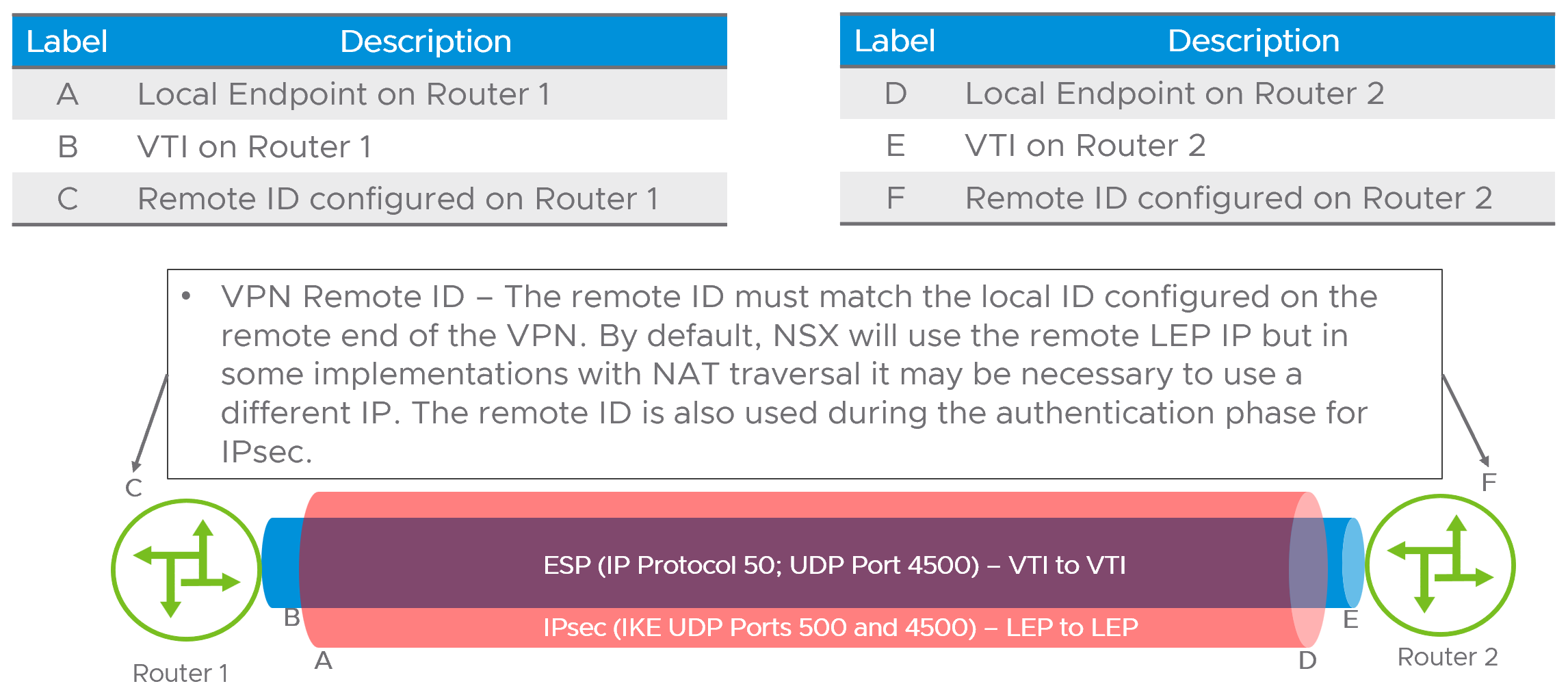
This article will discuss policy and route-based VPNs. From a NSX architecture perspective, VPNs will terminate on an IP address referred to as the Local Endpoint (LEP). The LEP is associated with the T1 it is created on and must be a unique IP address in the network. Internet Key Exchange (IKE) and Encapsulated Security Protocol (ESP) will use the LEP as the source and destination addresses for IPsec session. The diagram below illustrates the LEP, Virtual Tunnel Interface (VTI) and remote ID usage.
NOTE – It is important to differentiate between policy-based and route-based VPNs. A route-based VPN creates a single SA pair, also referred to as a tunnel, for all traffic, and then uses an IP interface on each end as a route destination. The routing can be dynamic (BGP, OSPF) or static. In the T1 VPN, only static routes are supported. Policy based VPNs do not use routing at all, but instead rely on policy matching applied to an interface to determine the traffic sent over the VPN tunnel. As such routing principles like shortest-prefix-wins do not apply. In general Policy VPNs require more configuration as both sides must be updated to reflect changes in the network topology.
Performance of T1 VPNs is a component of overall VMC on AWS networking performance. VMC on AWS uses a single edge cluster for all VPNs including T0 and T1. As a cumulative total, all VPNs performance is shared. In environments where the requirement for higher capacity VPNs is needed (greater than 2Gbps) large Edge appliances are recommended. A good reference for network performance in VMC on AWS can be found here in the VMC on AWS Management Cluster Planning designlet.
Configuration Steps
Configuring a VPN is a multi-step process with both policy and route-based VPNs sharing many of the same steps for configuration. This document will review three examples of VPNs.
- Route-based VPN over the Internet
- Route-based VPN over an AWS Direct Connect or VMware Transit Connect
- Policy based VPN over an AWS Direct Connect or VMware Transit Connect
Common VPN configuration steps must be completed in order as the step build upon themselves. The flowchart below outlines the process.

We will follow this process on an Internet based VPN in the example below. The topology used is a remote NSX VPN endpoint using the Internet to establish a route-based VPN to the Tenant-A Tier-1 router and is illustrated below.
Step 1 – Request Public IP address from AWS

Step 2 – NAT configuration on the NSX T0
In this configuration the LEP will be configured with the public IP address allocated from AWS. This is done to minimize confusion with address translation, but another address could be used for the LEP and NATted accordingly. It is recommended to use the public IP address for the LEP in a NoNAT configuration. NoNAT refers to a NAT configuration where the IP address is consistent end to end and not translated.

Step 3 – Create IPsec service

Step 4 – Create the Local Endpoint (LEP)

Step 5 – Configure IPsec session

Step 6 – Optional - Configuration of IPsec profiles
VMC on AWS has default IKE, IPsec and Dead Peer Detection (DPD) Profiles defined as shown below. If the use case requires different parameters, custom profiles can be configured and used.
Default IKE profile

Default IPsec profile

Default Dead Peer Detection (DPD) profile

Step 7 – Create Default CGW Firewall rules
The SDDC1-Tenant-A-LEP-NAT and SDDC2-Tenant-A-LEP-NAT groups contain their respective LEP IP addresses. These are not auto-created and the three protocols shown are the minimum required for the VPN to come up and pass traffic.

Step 8 – Set static route(s) on T1
The next hop is the IP address of the remote side of the virtual tunnel interface (VTI). In the use case for policy VPN, static routes are not needed.

Using the same flowchart for a route based VPN over an AWS Direct Connect or VMware Transit Connect . In use cases where the VPN uses AWS Direct Connect or VMware Transit Connect, be sure to configure route aggregation for the VPN LEP on the INTRANET connectivity endpoint.
Step 9 – Create Aggregation Prefix List and apply

The addition of VPNs directly to customer managed T1s opens new connectivity and tenancy models in VMware Cloud on AWS SDDCs.