
VMware Validated Solutions for Cloud Providers: Scale and Performance Guidelines for VMware Cloud Director 10.3-10.5
Introduction
The VMware Validated Solutions (VVS) for Cloud Providers: Scale and Performance Guidelines documents a pre-validated set of software components that simplify the deployment of a VMware Cloud Director® - based multitenant cloud in a predictable and efficient manner. While not a VMware Validated Solution by itself, it builds on the design guidance of the VMware Cloud Foundation™ documentation set and VMware Validated Solutions implemented on VMware Cloud Foundation.
Starting with VMware Cloud Foundation 4.3, the VMware Validated Design guidance for the SDDC components natively supported by the VMware Cloud Foundation automation is moved to the VMware Cloud Foundation documentation and the guidance for the solutions on top of VMware Cloud Foundation is now published under a new class of technical reference implementations called VMware Validated Solutions. VMware Validated Design documentation is discontinued.

Figure 1: VMware Cloud Foundation Documentation Map
Validated Solutions are a vetted portfolio of technical validated solutions designed to help build secure, high-performing, resilient and efficient infrastructure for applications and workloads deployed on VMware Cloud Foundation. Each VMware Validated Solution is fully validated by expert VMware solution architects and can be deployed out of the box with VMware Cloud Foundation. Each solution includes detailed design with design decisions, implementation procedures and, where applicable, automated steps using infrastructure-as-code using Terraform, PowerShell and operational guidance. These solutions also include a Time-to-Deploy value that provides an estimated time to deploy the solution, helping VI admins and architects to plan and deploy the solution.
The Scale and Performance Guidelines documents a validated VMware Cloud Provider Platform stack and associated scale and performance benchmarking captured during validation testing. It details what components are needed, which versions have received additional validation, and what kind of scale and performance VMware Cloud Providers can expect with a similar deployment. Additionally, the test data provided may be useful in extrapolating potential performance for smaller and larger scale deployments or different performance compute platforms.
With this document VMware Cloud Providers get clarity and predictability about which version of each software component of the VMware Cloud Provider Platform stack is recommended for use with a specific VMware Cloud Foundation version and associated VMware Validated Solutions. Each Scale and Performance version also includes a predictable support timeframe for the VMware Cloud Provider Platform stack, typically 12 – 18 months from the launch of the corresponding VMware Cloud Director major version release. This reduces the expense and time involved in deciding what components to upgrade when and to which version, so that the entire software stack stays in support and incompatible combinations are avoided.
It is not the current intent of Scale and Performance to push VMware Cloud Director to its absolute limits. For configuration maximums and limits, see VMware Cloud Director Configuration Maximums.
This document also includes the expected performance as observed by tenant users and VMware Cloud Provider administrators interacting with the VMware Cloud Director user interface and API.
The use of the new VMware Cloud Provider Lifecycle Manager™ is encouraged when deploying new environments. VMware Cloud Provider Lifecycle Manager is a tool for automating the deployment and lifecycle management of VMware Cloud Provider Platform components like VMware Cloud Director, VMware Chargeback, and VMware vCloud Usage Meter. VMware Cloud Provider Lifecycle Manager helps to deliver a prescriptive deployment architecture based on best practices and validated designs.
Benefits
VMware Cloud Providers who deploy the core technologies outlined in this VVS for Cloud Providers and who meet other programmatic requirements are also eligible to apply for the VMware Cloud Verified designation. Partners who are awarded the VMware Cloud Verified badge are promoted to VMware customers as specialists who can help them seamlessly run, manage, connect and secure their applications across private and public clouds in their familiar VMware cloud infrastructure environment. To receive the VMware Cloud Verified badge, VMware Cloud Providers must meet requirements and apply directly via the VMware Technology Validation page. For complete requirements and detailed application process, please refer to How to Achieve Cloud Verified and Cloud Verified Application Process documents.
One of the program requirements is to be running one of the software version stacks defined in this document as listed in TABLE 1. BILL OF MATERIALS. Please note that older stack versions listed in the table may be restricted to use for revalidation only. See the table footnotes for details. Products are expected to be patched with any required minor patch versions without impact to the Cloud Verified application process or status.
Audience
This document is intended for VMware Cloud Provider architects and technical leads responsible for planning and performing the deployment and upgrades of a VMware-based cloud environment.
Scope
This document addresses the following:
Interoperability stack
Provides a list of certified major product versions of all the component software comprising the software stack. Using the recommended major versions guarantees known support life of the stack as well as performance characteristics.
Scale and Performance
The certified solution stack provides known performance and scale characteristics and includes recommendations and guidelines for hardware and scale based on anticipated tenant demand. A VMware Cloud Director-based platform can be properly sized by following the sizing guidelines for hardware and scale based on anticipated tenant demand.
Sizing guidelines and software requirements
VMware Cloud Providers also benefit from clear guidelines for sizing hardware and software components to match their expected tenant load. While the Scale and Performance Guidelines does not cover every cloud configuration and size, it provides a sizing recommendation for a “typical” medium size cloud as representative of a broad set of VMware Cloud Providers. Data from VMware Cloud Providers was categorized into small (Profile A), medium (Profile B) and large (Profile C) size deployment profiles.
For additional guidance beyond the scope of this document see the complimentary documents that are part of the VMware Cloud Foundation documentation and VMware Validated Solutions documentation. Many of these are referenced throughout this document. Always refer to the VMware Product Interoperability Matrices as the authoritative resource for interoperability between the VMware software components mentioned in this guide. It is also important to remember that a compliant solution must follow all relevant security guidelines outlined in the product-specific and VMware Validated Solutions documentation.
Interoperability Stack (Bill of Materials)
The Bill of Materials table lists the pre-validated set of software components for Cloud Providers at the time of the Scale and Performance testing. While VMware Cloud Providers are free to use versions based on the full interoperability matrix or different combinations of VMware Cloud Provider Program software products, the specified stack guarantees a known predictable support time and specific performance and scaling characteristics. Performance and scaling information is supplied later this document. Products marked “Core” must be deployed to officially achieve Cloud Verified compliance but only need to adhere to the major product version listed below with the expectation that the latest patches will be applied by Cloud Providers as needed while adhering to the VMware Product Interoperability Matrix. See TABLE 9. VMWARE SOFTWARE VERSIONS for a detailed list of specific patch versions used in the test environment.
Table 1: Bill of Materials
|
Bill of Materials [1] |
|||||
|
Component |
Current Validated Stacks |
Core/ Optional |
Notes |
||
|
10.3 [2] |
10.4 |
10.5 |
|
|
|
|
VMware Cloud Foundation™ |
4.2 or 4.3 |
4.4 or 4.5 |
5.0 |
Optional |
|
|
VMware Cloud Foundation™ SDDC Manager™ |
4.2 or 4.3 |
4.4 or 4.5 |
5.0 |
Optional |
Bundled as part of VMware Cloud Foundation |
|
VMware vCenter Server® |
7.0 |
7.0 |
8.0 |
Core |
Bundled as part of VMware Cloud Foundation |
|
VMware ESXi™ |
7.0 |
7.0 |
8.0 |
Core |
Bundled as part of VMware Cloud Foundation |
|
VMware vSAN™ |
7.0 |
7.0 |
8.0 |
Core [3] |
Bundled as part of VMware Cloud Foundation |
|
VMware NSX® |
3.1 |
3.1 or 3.2 |
4.1 |
Core |
Bundled as part of VMware Cloud Foundation |
|
VMware Aria Suite Lifecycle™ (Formerly VMware vRealize Suite® Lifecycle Manager™) |
8.2 or 8.4 |
8.6 or 8.10 |
8.10 |
Optional |
Bundled as part of VMware Cloud Foundation |
|
VMware Aria Operations™ (Formerly VMware vRealize Operations™) |
8.5 |
8.6 or 8.10 |
8.10 |
Optional |
See the VVS Intelligent Operations Management and Health Reporting and Monitoring |
|
VMware Aria Operations™ for Logs (Formerly VMware vRealize® Log Insight™) |
8.2 |
8.6 or 8.10 |
8.10 |
Optional |
See the VVS Intelligent Logging and Analytics |
|
VMware Aria Operations™ for Networks (Formerly VMware vRealize® Network Insight™) |
6.1 |
6.5 or 6.8 |
6.8 |
Optional |
See VMware Aria Operations for Networks on Tech Zone |
|
VMware NSX® Advanced Load Balancer™ |
20.1 |
21.1 or 22.1 |
22.1 |
Optional |
See the VVS Advanced Load Balancing This product has strict patch version compatibility requirements. Check the VMware Product Interoperability Matrix for current patch interoperability information. |
|
VMware Workspace ONE Access |
3.3 |
3.3 |
3.3 |
Optional |
See the VVS Identity and Access Management |
|
VMware Cloud Provider Lifecycle Manager |
N/A |
1.3 or 1.4 |
1.5 |
Optional |
See the VMware Cloud Provider Lifecycle Manager Documentation |
|
VMware Cloud Director |
10.3 – 10.3.3.3 |
10.4 – 10.4.2 |
10.5 |
Core |
Deployed by VMware Cloud Provider Lifecycle Manager |
|
VMware vCloud® Usage Meter™ |
4.4+ |
4.5+ |
4.6+ |
Core |
UM can be any higher version. Deployed by VMware Cloud Provider Lifecycle Manager |
|
VMware Chargeback™ (Formerly VMware vRealize Operations Tenant App for VMware Cloud Director) |
2.6 |
8.6 or 8.10 |
8.10 |
Optional |
Deployed by VMware Cloud Provider Lifecycle Manager |
|
VMware Cloud Director Availability™ |
4.2 |
4.4 or 4.5 |
4.6 |
Optional |
|
|
VMware Cloud Director Container Service Extension |
3.1 |
3.1 or 4.0 |
4.1 |
Optional |
|
|
VMware Aria Automation Orchestrator™ (Formerly VMware vRealize® Orchestrator™) |
8.3 |
8.8 or 8.10 |
8.10 |
Optional |
Apply the latest available patch. |
|
VMware Cloud Director™ App Launchpad™ |
2.0 |
2.1 |
2.1 |
Optional |
|
|
VMware Cloud Director™ Object Storage Extension™ |
2.0 |
2.1 or 2.2 |
2.2 |
Optional |
|
|
VMware Cloud Director™ extension for Data Solutions™ |
|
1.0 or 1.1 |
1.2 |
Optional |
|
Scale and Performance
The Scale Profile B table defines a common environment like the environments of approximately 60% of all VMware Cloud Providers. While VMware Cloud Director is capable of a larger scale, the following profile is what is validated and benchmarked for Scale and Performance.
Table 2: Scale Profile B
|
Scale Profile B |
|
|
Parameter |
Value |
|
Number of tenants (Organizations in Cloud Director) |
400 |
|
Number of powered-on tenant virtual machines (with an OS installed) |
10,000 |
|
Number of physical data centers |
1 |
|
Number of VMware Cloud Director cells |
5 (1 primary, 2 standby cells, 2 application cells) |
|
Number of VMware vCenter Server instances managed by VMware Cloud Director |
3 VMware vCenter Server instances for resource capacity |
|
Maximum network latency from VMware Cloud Director to VMware vCenter Server and VMware NSX Manager™ |
Network RTT latency up to 150 ms |
|
Concurrent API operations |
Up to 128 concurrent users running operations against the VMware Cloud Director API |
|
Concurrent virtual machine migrations to VMware Cloud Director from tenant environments by VMware Cloud Director Availability |
100 |
Performance Characteristics
Environment Setup
The VMware Cloud Provider Platform environment is set up based on Scale Profile B.
Testing is performed at different levels of network latency from VMware Cloud Director cells to VMware vCenter Server and VMware NSX Manager to measure the impact of network latency on performance.
Performance and Throughput
The test throughput is measured as the number of operations performed over 30 minutes. The test was run with different test concurrency (32, 64, and 128) and network latency (0.3 ms, 40 ms, and 150 ms). During this test, a representative random sample of operations from the TABLE 11. VMWARE CLOUD DIRECTOR OPERATIONS is used.
Table 3: Performance and Throughput
| Performance and Throughput | ||||
| Network latency impact on operations | Successfully completed operations per minute | |||
| Concurrency (Number of concurrent users) | Latency (Milliseconds) | 10.3 | 10.4
| 10.5
|
| 32 | 0.3 MS | 147 | 128 | 130 |
| 40 MS | 138 | 127 | 127 | |
| 150 MS | 123 | 106 | 115 | |
| 64 | 0.3 MS | 274 | 243 | 235 |
| 40 MS | 259 | 223 | 230 | |
| 150 MS | 234 | 197 | 204 | |
| 128 | 0.3 MS | 453 | 401 | 378 |
| 40 MS | 435 | 380 | 356 | |
| 150 MS | 420 | 345 | 337 | |
API Latency
The API Operations Latency table shows average user observed latency (in seconds) for a selection of API operations at RTT = 0.3 ms. See TABLE 11. VMWARE CLOUD DIRECTOR OPERATIONS for the full list of operations invoked during this test.
Table 4: API Operations Latency
| API Operations Latency | ||||
| Concurrency Impact On Operations | Latency (Seconds) | |||
| Concurrency (Number of concurrent operations) | Operation | 10.3 | 10.4 | 10.5 |
| 32 | Instantiate a 150 MB vApp from a template | 20 s | 20 s | 20 s |
| Create an edge gateway | 8 s | 11 s | 12 s | |
| Create an independent disk | 9 s | 6 s | 6 s | |
| 64 | Instantiate a 150 MB vApp from a template | 21 s | 21 s | 22 s |
| Create an edge gateway | 7 s | 9 s | 13 s | |
| Create an independent disk | 10 s | 10 s | 7 s | |
| 128 | Instantiate a 150 MB vApp from a template | 25 s | 28 s | 28 s |
| Create an edge gateway | 9 s | 11 s | 16 s | |
| Create an independent disk | 13 s | 13 s | 9 s | |
Increasing the network RTT from 0.3 ms to 150 ms affects these numbers with the size of the effect varying significantly depending on the operation. With most API operations RTT increase from 0.3 ms to 150 ms caused the latency to increase by a factor of 2 or less.
Upload and Download Performance
The OVF upload and download times observed in the test environment vary depending on the different network latencies.
Table 5: OVF Upload and Download Times
| OVF Upload and Download Times | ||||
| Latency (Milliseconds) | Operation | 10.3 | 10.4 | 10.5 |
| 0.3 | OVF upload time in seconds (4 GB) | 292 | 272 | 263 |
| OVF download time in seconds (4 GB) | 194 | 195 | 188 | |
| 40 | OVF upload time in seconds (4 GB) | 320 | 297 | 271 |
| OVF download time in seconds (4 GB) | 195 | 196 | 195 | |
| 150 | OVF upload time in seconds (4 GB) | 323 | 304 | 282 |
| OVF download time in seconds (4 GB) | 197 | 198 | 196 | |
VMware Cloud Director Availability
The Time to Protect a VM in VMware Cloud Director Availability represents the time to establish replication of virtual machines of various sizes between a VMware Cloud Director and a DR target vCenter environment. 10 GB uplinks were configured between VMware vCenter Server and VMware Cloud Director. Network throughput was stable around 990 Mbps.
Table 6: Time to Protect a VM
| Time to Protect a VM | |||
| VM Size | Time to Protect | ||
| 10.3 | 10.4 | 10.5 | |
| 1 GB | 32 seconds | 38 seconds | 27 seconds |
| 10 GB | 3 minutes | 2 minutes 17 seconds | 1 minute |
| 100 GB | 18 minutes | 19 minutes 12 seconds | 16 minutes |
| 500 GB | 1 hours 45 minutes | 1 hours 38 minutes | 1 hours 30 minutes |
| 1 TB | 3 hours 20 minutes | 3 hours 23 minutes | 2 hours 48 minutes |
The Network Latency Impact on Migration Performance table displays how the network latency from VMware Cloud Director cells to VMware vCenter Server and NSX Manager impacts cold migration for virtual machines of 100 GB size.
Table 7: Network Latency Impact On Time To Protect (VM Size = 100 GB)
| NETWORK LATENCY IMPACT ON TIME TO PROTECT (VM SIZE = 100 GB) | |||
| RTT Latency between VMware vCenter Server and VMware Cloud Director | Time to Protect | ||
| 10.3 | 10.4 | 10.5 | |
| 0.3 ms | 18 minutes | 19 minutes 12 seconds | 16 minutes |
| 40 ms | 19 minutes | 20 minutes 27 seconds | 17 minutes |
| 150 ms | 21 minutes | 21 minutes 36 seconds | 18 minutes |
Sizing Guidelines
Many environment variables influence the number of hosts and CPU and memory resources required to run a cloud service based on VVS for Cloud Providers. It is impossible to give a precise formula for how much of each resource is required. The current effort focuses on demonstrating how our deployment setup behaves in terms of scale and performance under the defined test load.
The Scale Profile B captures the parameters of the load on the system in terms of number of tenants, organizations, VMs, network latency, and cloud management operations load. The results in terms of average response time, throughput, and uptime under these controlled conditions provide a starting point for Cloud Providers to estimate how much capacity is needed for their use cases. We strongly recommend that Cloud Providers extensively test each environment prior to production use to ensure that the performance meets the business SLAs.
VMware Cloud Director Virtual Appliance
The VVS for Cloud Providers recommends the use of a VMware Cloud Director virtual appliance. The virtual appliance includes an embedded PostgreSQL database fully managed by VMware Cloud Director with built-in replication for maintaining consistency between cells. A properly configured virtual appliance cluster is also resilient to failures of individual cells.
The recommended virtual appliance deployment includes 1 primary cell, 2 standby cells and 0 or more application cells. See the VMware Cloud Director Installation, Configuration, and Upgrade Guide for more details about the deployment, configuration, and operation of the virtual appliance.
For the purposes of VVS scale and performance benchmarking, the following Extra Large VMware Cloud Director appliance sizing configuration was used: 1 primary cell, 2 standby cells, 2 application cells. The Table 8. Management and Resource Component Sizing gives the details of memory and CPU capacity on each VMware Cloud Director appliance node.
Note that the amount of hardware and software resources deployed is meant to eliminate any resource-related constraints and allow to benchmark performance and stability of the software.
Determining how much hardware and software components are appropriate for a production deployment requires testing. There is no simple formula. However, the following VMware Cloud Director sizing guideline can be used as a starting point:
- Start with a Large VMware Cloud Director virtual appliance configuration with 1 primary and 2 standby nodes for environments of scale similar to Profile B.
- Benchmark the environment performance under a production-like load. Add application cells as needed to achieve desired throughput and response times.
The embedded PostgreSQL database is automatically configured. However, some post-deployment tuning might be needed for best performance. See the section VMware Cloud Director Appliance PostgreSQL Tuning for the database parameters used in this benchmarking.
Management and Resource Component Sizing
The following table summarizes sizing choices made for various management and resource components of the test environment.
Table 8: Management and Resource Component Sizing
|
Component |
Size [4] |
Resources |
Notes |
|
VMware Cloud Foundation SDDC Manager |
|
CPU: 4 RAM: 16 GB Storage: 816 GB |
|
|
Management VMware vCenter Server (VMware vCenter Server with an embedded Platform Services Controller) |
Small |
RAM: 19 GB CPU: 4 Storage: 480 GB |
1 management vCenter Server |
|
Resource VMware vCenter Server (VMware vCenter Server with an embedded Platform Services Controller) |
Large |
RAM: 37 GB CPU: 16 Storage: 1065 GB |
Resource VMware vCenter Server instances. VMware Cloud Foundation deploys medium VMware vCenter Server instances by default. The size is increased to Large |
|
|
Management Cluster RAM: 2.5 TB CPU: 364 Cores Storage: 21 TB vSAN, 14 TB iSCSI
Resource Clusters RAM: 1.7 TB CPU: 252 Cores Local Cluster Storage: 15 TB vSAN, 4 TB iSCSI Shared Storage: 10 TB iSCSI |
1 management cluster, 3 resource clusters |
|
|
VMware vSAN (deployed in Management VMware vCenter Server instance) |
|
21 TB |
1 VMware vSAN Cluster for Management VMware vCenter Server instance |
|
VMware vSAN (deployed in Resource VMware vCenter Server instances) |
|
15 TB (For each Resource VMware vCenter Server instance) |
1 VMware vSAN Cluster per Resource VMware vCenter Server instance (3 Resource VMware vCenter Server instances) |
|
VMware NSX |
Manager Size: Large
|
Manager RAM: 48 GB CPU: 12 Storage: 300 GB |
1 Management VMware NSX Manager Cluster (3 VMware NSX nodes) 3 Workload VMware NSX Manager Clusters (3 VMware NSX nodes for each Workload VMware NSX Manager Cluster) |
|
Edge Size: Large |
Edge RAM: 32 GB CPU: 8 Storage: 200 GB |
1 Management VMware NSX Edge Cluster (2 VMware NSX Edge nodes) 3 Workload VMware NSX Edge Clusters (2 VMware NSX Edge nodes for each Workload VMware NSX Edge Cluster) |
|
|
VMware Cloud Provider Lifecycle Manager™ |
|
CPU: 2 RAM: 8 GB Storage: 88 GB NFS storage: 100GB |
|
|
VMware Cloud Director |
Virtual appliance Extra Large Configuration 1 Primary (Large) 2 Standby cells (Large) 2 Application Cells (Large)
|
Each Primary and Standby Cell RAM: 32 GB CPU: 24 Storage: 202 GB
Each Application Cell RAM: 8 GB CPU: 8 Storage: 132 GB |
1 TB VMware vSAN File Service NFS storage for the VMware Cloud Director transfer service. Increased root partitions to 50 GB for logs Increased PostgreSQL database disks to 150 GB
|
|
VMware Cloud Director Database |
|
|
Database is embedded with the appliance |
|
VMware Cloud Director Availability |
1 Cloud Replication Management Appliance |
CPU: 2 RAM: 4 GB Storage: 10 GB |
|
|
1 Cloud Replicator Appliance |
CPU: 4 RAM: 6 GB Storage: 10 GB |
|
|
|
1 Cloud Tunnel Appliance |
CPU: 2 RAM: 2 GB Storage: 10 GB |
|
|
|
5 On-Premises Appliances |
CPU: 4 RAM: 4 GB Storage: 10 GB |
|
|
|
VMware Cloud Director Container Service Extension |
|
CPU: 2 RAM: 4 GB Storage: 55 GB |
|
|
VMware Cloud Director AMQP (Rabbit MQ) |
|
|
Cluster with 2 nodes |
|
VMware Cloud Director Metrics Database (Cassandra) |
|
CPU: 4 RAM: 8 GB Storage: 120 GB |
Cluster with 4 nodes 100GB Dedicated for Keyspace data |
|
VMware Aria Operations for Logs (Formerly VMware vRealize Log Insight) |
Primary Large (1 node)
Worker Large (2 nodes) |
Primary CPU: 16 RAM: 32 GB Storage: 1030 GB
Worker CPU: 16 RAM: 32 GB Storage: 1030 GB |
Use the VMware Aria Operations for Logs Sizing Estimator
|
|
VMware Aria Operations for Networks (Formerly VMware vRealize Network Insight) |
Platform Large (3 nodes)
Collector Large (3 nodes) |
Platform CPU: 12 RAM: 48 GB Storage: 1 TB
Collector CPU: 16 RAM: 8 GB Storage: 215 GB |
Use the VMware Aria Operations for Networks System Recommendations and Requirements |
|
VMware vCloud Usage Meter |
Standard |
CPU: 2 RAM: 8 GB Storage: 60 GB |
|
|
VMware Workspace ONE Access Identity Manager™ |
|
CPU: 2 RAM: 6 GB Storage: 60 GB |
Use the Workspace ONE Access System and Network Configuration Requirements |
|
VMware Aria Automation Orchestrator (Formerly VMware vRealize Orchestrator) |
|
CPU: 4 RAM: 12 GB Storage: 200 GB |
|
|
VMware Aria Automation Orchestrator plug-in for VMware Cloud Director |
|
|
|
|
VMware Aria Operations (Formerly VMware vRealize Operations Manager) |
Primary Size: Large
Primary Replica Size: Large
Data Size: Large |
Primary RAM: 48 GB CPU: 16 Storage: 274 GB Primary Replica RAM: 48 GB CPU: 16 Storage: 274 GB Data RAM: 48 GB CPU: 16 Storage: 274 GB |
1 Primary, 1 Primary Replica, 1 Data node |
|
VMware Aria Suite Lifecycle™ (Formerly VMware vRealize Lifecycle Manager) |
|
CPU: 2 RAM: 6 GB Storage: 148 GB |
Use the vRealize Suite Lifecycle Manager Design for VMware Cloud Foundation |
|
VMware Aria Management Pack for VMware NSX |
|
|
Native Management Pack |
|
VMware Aria Management Pack for VMware vSphere |
|
|
Native Management Pack |
|
VMware Aria Operations Management Pack for Logs (Formerly VMware vRealize Operations Management Pack for VMware vRealize Log Insight) |
|
|
Native Management Pack |
|
VMware Aria Management Pack for VMware Cloud Director |
|
|
|
|
VMware Aria Management Pack for VMware vSAN |
|
|
Native Management Pack |
|
VMware Chargeback (Formerly VMware vRealize Operations Tenant App for VMware Cloud Director) |
|
CPU: 2 RAM: 8 GB Storage: 72 GB |
|
|
VMware Cloud Director App Launchpad |
|
|
Use the VMware Cloud Director App Launchpad External Components Requirements |
|
VMware Cloud Director Object Storage Extension |
|
|
Use the Deploying VMware Cloud Director Object Storage Extension |
|
VMware NSX Advanced Load Balancer |
|
|
Use the Sizing Compute and Storage Resources for NSX Advanced Load Balancer Controller(s) Use the Sizing Compute and Storage Resources for NSX Advanced Load Balancer Service Engine(s) |
Appendix A – Test Environment and Benchmarking Methods
Test Environment
The test environment includes a management cluster, resource clusters (70% of workloads on vSAN, 30% on iSCSI storage) and a test driver.
Management Cluster
All management components were deployed in a management cluster of 13 physical servers (Cisco UCSC-C240-M5SX). Each server is configured with 192 GB RAM, 28 cores, and vSAN supported SSDs to make up 21 TB vSAN as well as 14 TB iSCSI attached storage.
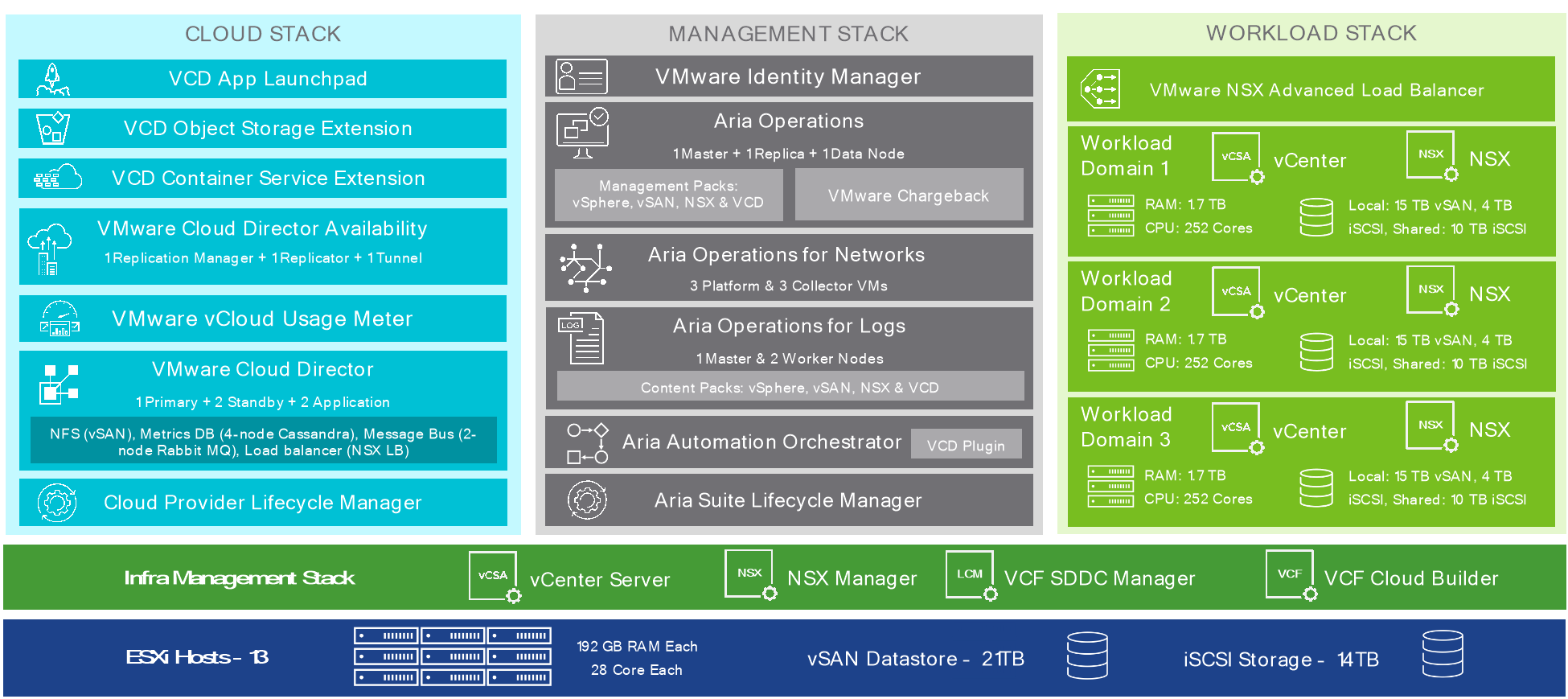
Figure 2: Management Component Deployment
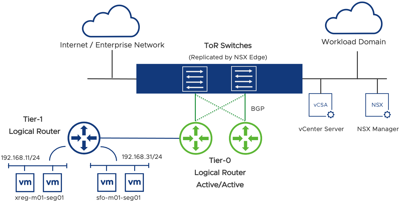
Figure 3: Management Cluster Networking
Resource Cluster
This is where the Tenant Organizations and workload virtual machines were created.
- 27 physical servers (Cisco UCSC-C240-M5SX)
- Each physical server is with 192 GB RAM and 28 cores, each with vSAN supported SSDs
- 15.72 TB vSAN, 10 TB iSCSI (Shared) and 4TB iSCSI for each cluster
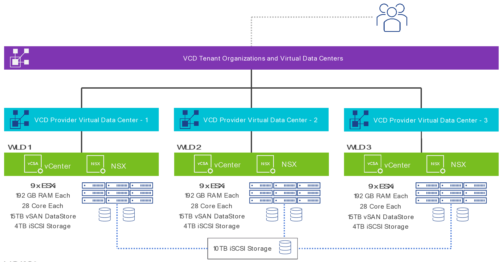
Figure 4: Resource Cluster Setup
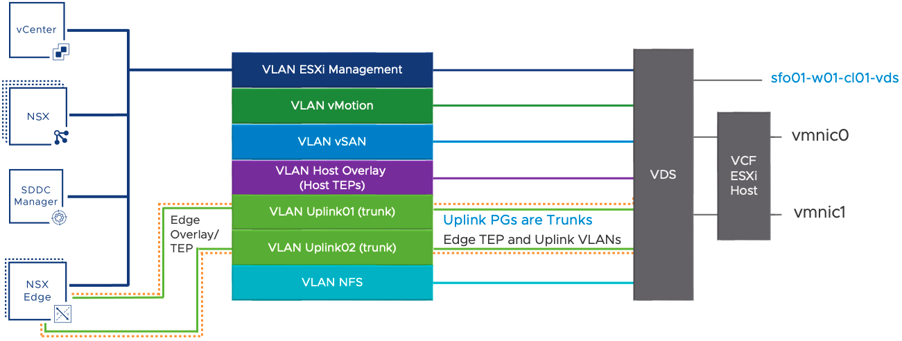
Figure 5: Resource Cluster Networking
Software Versions
The table below provides a detailed list of VMware software versions and patch levels used for each test run.
Table 9: VMware Software Versions
| Component | Tested Versions and Patch Levels | |||
| 10.3 | 10.4 | 10.4.1 | 10.5 | |
| Management VMware vCenter Server (VMware vCenter Server with an embedded Platform Services Controller) | 7.0U1c | 7.0U3d | 7.0U3h | 8.0U1a |
| Resource VMware vCenter Server (VMware vCenter Server with an embedded Platform Services Controller) | 7.0U1c | 7.0U3d | 7.0U3h | 8.0U1a |
| VMware ESXi™ | 7.0U1d | 7.0U3d | 7.0U3g | 8.0U1a |
| VMware vSAN (deployed in Management VMware vCenter Server instance) | 7.0U1d | 7.0U3d | 7.0U3g | 8.0U1a |
| VMware vSAN (deployed in Resource VMware vCenter Server instances) | 7.0U1d | 7.0U3d | 7.0U3g | 8.0U1a |
| VMware NSX | 3.1.0 | 3.1.3.7.4 | 3.2.1.2 | 4.1.0.2 |
| VMware Cloud Provider Lifecycle Manager | N/A | 1.3 | 1.4 | 1.5 |
| VMware Cloud Director | 10.3 | 10.4 | 10.4.1 | 10.5 |
| VMware Cloud Director Database (PostgreSQL) | 10.17 | 10.20 | 14.5 | 14.7 |
| VMware Cloud Director Availability | 4.2 | 4.4 | 4.5 | 4.6 |
| VMware Cloud Director Container Service Extension | 3.1 | 3.1.4 | 4.0 | 4.1 |
| VMware Cloud Director AMQP (Rabbit MQ) | 3.8.14 | 3.10.5 | 3.11.2 | 3.12.1 |
| VMware Cloud Director Metrics Database (Cassandra) | 3.11.10 | 4.0.4 | 4.0.7 | 4.0.7 |
| VMware Cloud Foundation SDDC Manager | 4.2 | 4.4.1 | 4.5 | 5.0 |
| VMware Aria Operations for Logs | 8.2 | 8.6.2 | 8.10 | 8.10.2 |
| VMware Aria Operations for Networks | 6.1 | 6.5.1 | 6.8 | 6.8 |
| VMware vCloud Usage Meter | 4.4 | 4.5.0.1 | 4.6 | 4.7.0.1 |
| VMware Workspace ONE Access Identity Manager™ | 3.3.4 | 3.3.6 | 3.3.6 | 3.3.7 |
| VMware Aria Automation Orchestrator | 8.3 | 8.8 | 8.10 | 8.10.2 |
| VMware Aria Automation Orchestrator plug-in for VMware Cloud Director | 10.0.0.1 | 10.3.0.1 | 10.3.0.1a | 10.3.0.1a |
| VMware Aria Operations | 8.5 | 8.6.2 | 8.10 | 8.10.2 |
| VMware Aria Suite Lifecycle Manager | 8.2 Patch 2 | 8.6.2 | 8.10 | 8.10.1 |
| Management Pack for VMware NSX | 8.5 | 8.6 | 8.10 | 8.10.2 |
| Management Pack for VMware vSphere | 8.5 | 8.6 | 8.10 | 8.10.2 |
| Management Pack for VMware vRealize Log Insight | 8.5 | 8.6 | 8.10 | 8.10.2 |
| Management Pack for VMware Cloud Director | 5.5 | 8.6.1 | 8.10 | 8.10.2 |
| Management Pack for VMware vSAN | 8.5 | 8.6 | 8.10 | 8.10.2 |
| VMware Chargeback | 2.6.1 | 8.6.2 | 8.10 | 8.10.2 |
| VMware Cloud Director App Launchpad | 2.0 | 2.1.1.2 | 2.1.2 | 2.1.2.1 |
| VMware Cloud Director Object Storage Extension | 2.0 | 2.1.1 | 2.2 | 2.2.2 |
| VMware NSX Advanced Load Balancer | 20.1.4 | 21.1.4 | 22.1.2 | 22.1.4 |
VMware Cloud Director Appliance PostgreSQL Tuning
PostgreSQL database parameters were set as follows:
shared_buffers = '7GB';"
effective_cache_size = '21GB';"
work_mem = '8MB’;"
max_worker_processes = '24';"
maintenance_work_mem = '1GB';"
For some earlier 10.3 versions of VMware Cloud Director appliance these additional PostgreSQL database parameters were set as follows and have now become default settings for later versions and 10.4:
wal_buffers = '16MB';"
max_wal_size = '2GB';"
min_wal_size = '2GB';"
checkpoint_timeout = '5min';"
checkpoint_completion_target = '0.9';"
See Modify the PostgreSQL Configurations in the VMware Cloud Director Appliance from the VMware Cloud Director documentation.
VMware vCenter Server Sizing
The default size for a workload VMware vCenter Server per VMware Cloud Foundation deployment is medium. To support scale profile B, the size is changed from medium to large.
VMware NSX Tuning
The http properties value of API rate limit, global-api-concurrency, client-api-concurrency-limit on VMware NSX Manager must be increased to:
500 for global-api-concurrency-limit
450 for client-api-concurrency-limit
500 for client-api-rate-limit
To update the http properties values on VMware NSX Manager:
- Connect to VMware NSX manager as admin user.
- Run the following commands on VMware NSX Manager:
set service http global-api-concurrency-limit 500
set service http client-api-concurrency-limit 450
set service http client-api-rate-limit 500
Data Plane Rx Ring Size value for all Workload Domain VMware NSX Edge Transport Nodes must be increased to 2048. To Update Data Plane Rx Ring Size:
- Connect to VMware NSX Edge Transport Node as admin user.
- Run the following commands on VMware NSX Edge Transport Node:
set dataplane ring-size rx 2048
restart service dataplane
Test Driver
The test driver suite is run from this environment against the load balanced VIP of the VMware Cloud Director cells.
- 4 CPU, 8 GB memory, CentOS 7.3
Benchmarking Methods
The testing process is focused primarily on verifying and measuring environment behavior for:
- Scale - Verify whether the environment meets the Scale Profile B requirement of 10,000 powered-on virtual machines.
- Performance - Measure the operation latency and throughput when the environment is running at scale (10,000 powered-on virtual machines).
- Uptime - Verify that the environment can operate at scale with reasonable performance for a long time.
The remainder of this section details the exact methods used for testing and measurement.
Scale Test
Scale was carried out with a mix of manual operations and JMeter test tool-based script operations by using the following steps:
- Create 400 Tenant Organizations in VMware Cloud Director.
- Create 15,000 virtual machines and power on 10,000 virtual machines across these 400 tenant organizations. All virtual machines were running CentOS with 2 GB disk, 0.5 GB memory.
- A sample of VMware Cloud Director operations were carried out to verify that the system behaves normally at this scale.
Performance Test
Performance tests were done by performing a well-known distribution of VMware Cloud Director operations with the help of an internal test tool. For the complete operation list, see TABLE 11. VMWARE CLOUD DIRECTOR OPERATIONS.
The following were the key steps in performing and measuring the operations:
- Scaled up the environment as outlined in the previous section.
- After the environment was at scale, run a continuous stream of operations for 30 minutes with following distribution:
- 35-40% vApp operations such as instantiate, deploy, edit, clone, and delete.
- 25% storage-centric operations such as create, attach, detach, and delete disk.
- 15% networking-related operations, such as create and delete gateway, routed networks, and firewall configurations.
- 5% create and delete Orgs, users, catalogs, and virtual data centers.
- Operations were performed by using VMware Cloud Director local users of different roles (such as vApp Author, Org Admin, and System Admin) with 10% admin roles and 90% user operation roles.
- Given that most of the operations are asynchronous, the test tool monitors the task returned by VMware Cloud Director to get a completion status and performance time details.
- Steps 2 to 4 were repeated with 32, 64, and 128 concurrent users to ascertain the ability of the system to deal with concurrent operation invocation.
- Step 5 was repeated for following latency (between VMware Cloud Director and VMware vCenter Server / VMware NSX Manager) values (achieved by artificial latency injection with a tool):
- 0.3 ms (default)
- 40 ms
- 150 ms
Uptime Tests
Uptime tests involved running the environment (based on Scale Profile B) for 5 days and running a constant stream of API calls covering a representative set of operations. The purpose of the test is to establish the API call success rate and system uptime.
- Tests ran continuously for 5 days.
- API workflows were triggered by 100 concurrent clients, each client would invoke an operation roughly every 20 seconds. 10,000 powered on VMs
- No artificial latency injection was done.
Table 10: Uptime Test Results
| Uptime Test Results | |||
|
| 10.3 | 10.4 | 10.5 |
| Total Operations completed over 5 days | 2,166,574 | 2,258,080 | 2,487,101 |
| Average test throughput over 5 days | 301 Ops/min | 313 Ops/min | 345 Ops/min |
| Success rate | 99.91% | 99.93% | 99.94% |
List of Operations
For performance benchmarking, API test clients ran a predetermined distribution across different types of VMware Cloud Director operations as described in the following tables.
Table 11: VMware Cloud Director Operations
| VMWARE CLOUD DIRECTOR OPERATIONS | |
| Component | Operations |
| vApp |
|
| Network |
|
| Management |
|
| NSX Management |
|
| Datastore |
|
| OVF |
|
Appendix B – FAQ
- Q. How frequently will the Scale and Performance be updated?
A. We expect to release an updated Scale and Performance with every major VMware Cloud Director release.
- Q. How is this document related to the VMware interoperability matrix?
A. The benchmarked stack is a subset of the full interoperability matrix and reflects the exact components we validated and benchmarked in this exercise. The full interoperability includes many more products and versions than what is tested in this exercise.
- Q. How is the Scale and Performance related to VMware Cloud Foundation?
A. VMware Cloud Foundation is being used to deploy VMware vCenter Server, VMware vSAN, and VMware NSX. It is not required that partners use VMware Cloud Foundation, but it is a supported and recommended option.
- Q. Is Scale and Performance suitable for greenfield environments or brownfield environments?
A. Any environment can be made compliant by simply upgrading all its components to the versions listed in the Scale and Performance Bill of Materials. There is no other qualification.
- Q. How can we provide input/recommendations for future versions of this doc?
A. Contact the VMware Cloud Director team at vcd-feedback@vmware.com or reach out to your VMware account team and pass your feedback through them.
- Q. What is the support model for an environment configured according to these guidelines?
A. Each component of the Cloud Provider Platform stack is supported according to its support lifecycle. A cloud deployment compliant with the Bill of Materials is in support for at least 12 months after the Scale and Performance release date.
Update History
| Revisions | Description |
| September 2023 | Updates for VMware Cloud Director 10.5 and VMware Cloud Foundation 5.0 validation |
| February 2023 | Updates for VMware Cloud Director 10.4.1 and VMware Cloud Foundation 4.5 validation |
| August 2022 | Initial version. |
[1] These are the recommended set of products, but this is not a full interoperability matrix. VMware Cloud Director is supported with multiple versions of each product listed but in each benchmarking test suite we used a specific product version. Test results generally apply to all patches within the specified major version of each component. See the VMware Product Interoperability Matrix for full interoperability information.
[2] Eligible for existing VMware Cloud Verified partner revalidation only.
[3] vSAN-based storage must be deployed in at least one cluster (either management or workload).
[4] Unless otherwise noted the component sizing applies to all VVS versions.