
VMware Cloud Disaster Recovery - Networking Field Guide
Overview
Welcome to the VMware Cloud DR Networking Field Guide, a comprehensive resource for anyone tasked with planning, implementing, and maintaining network infrastructure before and in the aftermath of a disaster.
Disasters, whether natural or man-made, can strike at any time, often leaving business applications inoperable and organizations unable to communicate and access critical information. In these situations, having a well-designed and tested disaster recovery plan can make all the difference in minimizing downtime and ensuring business continuity.
This guide provides you with the knowledge, tools, and references to other resources necessary to develop and implement an effective networking infrastructure for your disaster recovery strategies.
Introduction
In this guide we will cover the general networking areas related to enabling VMware Cloud DR, developing disaster recovery plans, testing those plans, and managing the networks when needed for actual recovery purposes.
We will cover two main scenarios for networking considerations. One is for handling a site DR scenario, where some or all primary production site service is down, and the business applications are failed over to the cloud-based recovery site to run production operations in a disaster recovery mode until the original site is usable again. The second scenario is when the primary site is still available but has been impacted by ransomware and the remediation task will be conducted in the safety of the cloud-based Isolated Recovery Environment (IRE).
As each customer’s environment is specific to the needs and configuration of the business, this guide will make some simplifications and assumptions to get you started and direct you to the best resources.
Purpose of This Guide
This Field Guide is organized into the typical tasks or topics involved in setting up and operating the VMware Cloud DR and VMware Ransomware Recovery solutions. It is not intended to be a step-by-step manual for setup – there are many excellent resources to help with that, and this guide will often point you to those additional resources. With that in mind, you will find many hyperlinks within this guide to those other resources that will help fill in the details and guide you along the topics.
As a Field Guide, the intent is to help augment, not replace, the information already provided in the VMware Cloud DR product documentation.
As we always recommend, a good practice is to check the latest release notes for any updates. They can be found here: VMware Cloud DR Release Notes
Audience
This guide is primarily directed to the DR infrastructure administrators responsible for configuration and operation of the disaster recovery solution between the production (protected) sites and the failover (recovery) site in VMware Cloud on AWS.
This guide will also contain useful information for network administrators responsible for supporting the environments configured for the VMware Cloud DR solution.
This guide is not intended to be a detailed security guide but will cover some networking-related topics that may relate to overall security considerations.
Basic DR Networking Review
Let’s start with a high-level review of the basic disaster recovery topology to identify the terminology and some typical requirements. With VMware Cloud DR, the networking configuration will be between a Protected Site (the source data center) and the Recovery Site (the destination failover data center).
The Protected Site is an on-premises vSphere/vCenter-based environment, another VMware Cloud on AWS SDDC, or possibly a Google Cloud VMware Engine (GCVE) vSphere/vCenter-based environment (Tech Preview).
For the Protected Site, we focus mainly on the setup and connectivity of the following components:
- DRaaS Connectors – these provide connectivity between the site and the cloud-based DR components.
- vCenter – provides the VM inventory that will be protected.
- vSphere hosts – provide access to the underlying VMDK files for the protected VMs.
- VMs – the basic building block of business applications and the key item/unit for recovery.
For the Recovery Site, we focus mainly on the setup and connectivity of the following components:
- Scale-out Cloud File System (SCFS) – also called Cloud File System – holds the recovery point snapshots of the protected VMs.
- SDDC (vCenter) – provides access to the vCenter/vSphere virtualization infrastructure for the DR site. This includes the VSAN storage and the NSX networking.
- VMs – the recovered components that make up the business applications.
In addition to the core infrastructure components mentioned above, we also consider related networking services such as AD/DNS/DHCP and subnets/VLANs to the degree they are affected by the disaster recovery setup and operations. This guide is not intended to be a guide on how to set up these core services. For a discussion on possible DNS options working with VMware Cloud on AWS, check out this resource: VMware Cloud DNS Architectures.
For the setup and operation of a multisite DR solution like VMware Cloud DR, we break the networking considerations down into the following key areas so we can address the DR-specific considerations:
- Protection – connectivity of the Protected Site to the Recovery Site for basic VM protection (recovery point snapshot and replication).
- Infrastructure – connectivity to the site components to configure and manage the infrastructure.
- Application – connectivity between VMs running at different sites to enable proper business application functionality.
- End-User – end-users (customers) connectivity to the business applications running in the configured sites.
This breakdown is generally depicted in the following diagram:
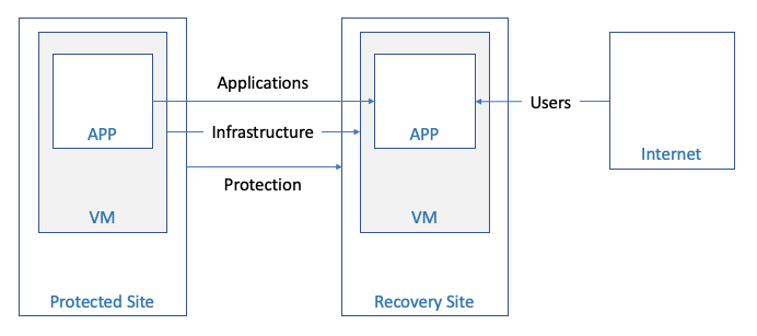
Figure 1 - Connectivity Overview
TASKS
Determine which components identified above will need to be accessed for the setup of the DR solution, management of the Protected and Recovery sites, and connectivity to key VMs needed to support the overall DR configuration. Note the system name (e.g., FQDN), IP addresses, subnet/VLAN configuration, and administrator access credentials – as these will be needed during the product setup and used during the recovery plan construction.
VMware Cloud on AWS Networking Options
VMware Cloud DR leverages the VMware Cloud on AWS platform to host the Software Defined Data Center (SDDC) for all recovery operations, whether for site DR or the ransomware recovery Isolated Recovery Environment (IRE). For some implementations, this may be the first time you are working with or connecting to VMware Cloud on AWS.
You have multiple ways to connect an on-premises production, protected site to VMware Cloud on AWS. For the beginner, here are some great resources for setting up the Recovery SDDC in VMware Cloud on AWS:
- VMware Cloud on AWS – Getting Started documentation
- VMware Cloud on AWS Launchpad
- VMware Cloud on AWS Tech Zone
There is a good explanation of these SDDC access basics in this short VMC networking overview video and a good write-up in this VMC internet access blog.
There are also great video resources like Network Connectivity and Network Overview for VMware Cloud on AWS on the VMC YouTube channel and even more helpful videos in the VMware Cloud on AWS: Quick Start playlist.
TASKS
There are basically 3 methods for connecting the on-premises data center environment to the resources in VMC on AWS. Each approach has advantages and trade-offs concerning complexity, cost, performance, and security. We recommend that you review these choices with your global network team for the best implementation option. The connectivity methods, from simplest to most complex, are:
- Rely on the SDDC management gateway firewall rules to allow access to the SDDC management network over the public internet and prevent access by untrusted sources – this may be the simplest option and may be appropriate for some use cases but is inherently less secure than the others listed below.
- Configure a VPN Connection between your SDDC and On-Premises Data Center – to enable encrypted connectivity over the public internet.
- Configure AWS Direct Connect between your SDDC and On-Premises Data Center – providing a dedicated connection for public and private virtual interfaces (VIFs).
Connecting the Production Site for Protection
To protect the VMs in an on-premises data center, a DRaaS Connector is installed, as an OVA, into the site. The DRaaS Connector establishes the replication connection over the network to the SCFS (Scale-out Cloud File System). The connection is over the public internet or a private dedicated network (AWS Direct Connect), depending on how the organization wants to connect to the VMC on AWS infrastructure.
To protect a VMware Cloud on AWS SDDC, the DRaaS Connector is installed into the Protected Site side SDDC with the VMs to be protected. The networking and firewall port management between the source (protected) SDDC and the destination (recovery) SDDC can be configured manually or automated by the Orchestrator. The DRaaS Connector typically gets configured with DHCP from the source side SDDC network configuration.
The system and network requirements for connecting a Protected Site are covered in the product documentation in more detail here. It is over this network configuration that the VM recovery point snapshots will be replicated to the Cloud File System. It is useful to note that there is an initial seeding of the first full copy of the VM that goes over this network. This first copy typically takes longer than subsequent incremental snapshot recovery points. The subsequent snapshots of the protected VMs are based on the changed blocks between snapshots. The data is compressed and encrypted as it is transmitted from the Protected Site to the Cloud File System.
TASKS
Review the latest product documentation on protected site setup for any changes to the networking requirements for each site being added. VMware Cloud DR can support multiple On-Premises or VMware Cloud on AWS SDDC connections to the Recovery Site.
Determine how the DRaaS Connectors will be deployed, using DHCP or static IP. For static IP setup of the DRaaS Connector, ensure you have the associated networking details and the IP address. This includes the netmask, gateway, and DNS servers for static IP resolution.
Determine how many DRaaS Connectors will be deployed for each Protected site – up to the max configuration per VMware Cloud DR instance (VMware Config Max Tool).
Creating the SDDC
The Recovery site administrator is responsible for the initial creation and ongoing management of the Recovery SDDC in VMware Cloud on AWS.
The SDDC can be created from the VCDR UI or directly in the VMC console. When created from the VCDR UI, the Cloud File System location (Region and AZ) drives the choice for the AWS Region and AZ for the SDDC – which must be the same as the Cloud File System so that the xENI network connection can be established for the “Live Mount” recovery datastore.
If the Recovery SDDC is created from the VMC console interface, the location (Region and AZ) of the Recovery SDDC should match the Cloud File System, or you will not be able to attach the Cloud File System as the recovery datastore.
In either case, the AWS account for setting up the SDDC-SCFS connection will need at least one VPC and the appropriate subnets (i.e., in the connected AZ) configured for the Recovery SDDC configuration.
TASKS
To improve flexibility of selecting an appropriate AZ, we recommend defining VPC subnets for each AZ in the region where the Recovery SDDC and Cloud File System are deployed.
Consider this VMware Fling (SDDC Import/Export for VMware Cloud on AWS) for situations where an SDDC is created, configured and tested, and removed. This Fling can help with saving and restoring the configuration of the SDDC, including network setup.
Accessing the SDDC
A newly created SDDC has no external management access defined. To connect to the SDDC and manage its configuration for DR purposes (e.g., folders, resources, tags) you will need to gain login access to the SDDC – typically for the “cloudamin@vmc.local” user.
TASKS
The simplest approach to connecting to the Recovery SDDC is to grant firewall access to the desired external systems through the VMC console network administration UI.
Here is a good VMware blog resource on Networking and Security in VMware Cloud on AWS.
Adding Segments to the SDDC
You must manually create network segments in the Recovery SDDC to support the VM workloads that will be running there in a DR event. Recovery Site networks are not automatically constructed from VMware Cloud DR operations. Network segments provide the mechanism for VMs placed on these segments to communicate with each other.
Network segments can be added from the VCDR UI or the VMC console network administration UI.
There needs to be a 1:1 network segment mapping in the Recovery plans for each Protected Site network segment to a separate Recovery SDDC network.
For better controlled, non-disruptive Recovery Plan testing, you can configure additional network segments specifically for Recovery Plan testing. These network segments provide a location to map VMs during Recovery Plan testing without interacting or interfering with production networks and services. Testing network segments might get configured as Disconnected for even more isolation.
TASKS
Define a network segment in the Recovery SDDC for each network segment that exists in the Protected site VM inventories. This will be important in completing the Recovery Plan mapping activities.
Define test network segments for isolated testing activities available through the Recovery Plan test mode operations.
Outbound Connectivity from the SDDC
The default network setup for an SSDC is not configured for traffic to flow into or out of the VM network segments defined in the SDDC. Using the NSX Networking and Security interface of the SDDC management console, you can modify the configuration to enable the desired network access. This is done primarily through the gateway firewall methods. The Management gateway firewalls control infrastructure components (e.g., vCenter, vSphere hosts, etc.) access to the internet. The Compute gateway firewalls control workloads VMs (e.g., failed over application VMs) access to the internet.
For each organization, it is important to define the appropriate firewall rules for the access needed both into and out of the SDDC environment.
Using the NSX capabilities, it is recommended to use Groups for better asset organization and granularity of control.
TASKS
Determine which systems and VMs will need internet access outside the SDDC and on which network segments they will reside. Create the appropriate NSX Inventory Groups and Gateway Firewall constructs to allow the identified VMs access to the internet networks outbound form the SDDC.
Use the principle of least privilege when determining what level of network access is being configured. The principle of least privilege is an information security concept that maintains that a user or entity should only have access to the specific data, resources, and applications needed to complete a required task.
Inbound Connectivity to the SDDC
Another consideration of the overall DR network design and implementation is determining how application VMs will be reached from outside the SDDC once running in the Recovery SDDC. There are a couple of options for managing this type of connection depending on the scope of the target IP of the failed over VM. If access to that VM will be over a published, public IP address, you can request and configure a public IP address into the NSX network configuration within the SDDC.
In some network configurations, the VM may be accessed directly through its exposed interface in the SDDC. This can be achieved through appropriate gateway firewall inbound rules.
Inbound connectivity may also be achieved through a published VPN configuration.
TASKS
Determine which VM workloads must be accessed from the internet once failed over to the Recovery SDDC. For each of these systems, construct the appropriate inbound pathway to that VM. This is another setup where you should use the principle of least privilege when determining what level of network access is being configured.
Inter-Site Application Connectivity
The remaining type of DR network design that needs to be considered is how to handle communications between the VMs that are still in the Protected site and those that have failed over to the Recovery sites. This is important when some business/application services are still running in the Protected site and need to communicate with VMs that have failed over to the DR site. This hybrid cloud network configuration usually takes advantage of basic layer 2 VPN methods for connecting the sites. The connection can be further isolated from the internet with a Direct Connect dedicated setup.
There is a good resource on VMware Cloud on AWS Networking and Security that goes into the details for setting up connectivity between your existing on-premises VMware environments and VMware Cloud on AWS configurations.
TASKS
Determine the scope of the disaster failover needs – which VMs will run in the Recovery site and construct the Protection Groups and Recovery Plans to address these VMs that are protected and failed over together. For any partial failover configurations where there are resources that do not fail over to the cloud-based Recovery site, make sure that appropriate connections are identified and designed into the topology of the Protected site to Recovery site networking.
Network Mapping for Testing
One of the distinct advantages of the VMware Cloud DR solution is the ability to create separate testing configuration options in the same Recovery Plan and enable even more control over non-disruptive testing of these plans during normal operations.
When adding network segments as discussed above, you can create additional testing network segments and map those in the Recovery plans specifically for testing purposes. This option is shown in the Recovery plan configuration UI as shown marked in red in the figure below:
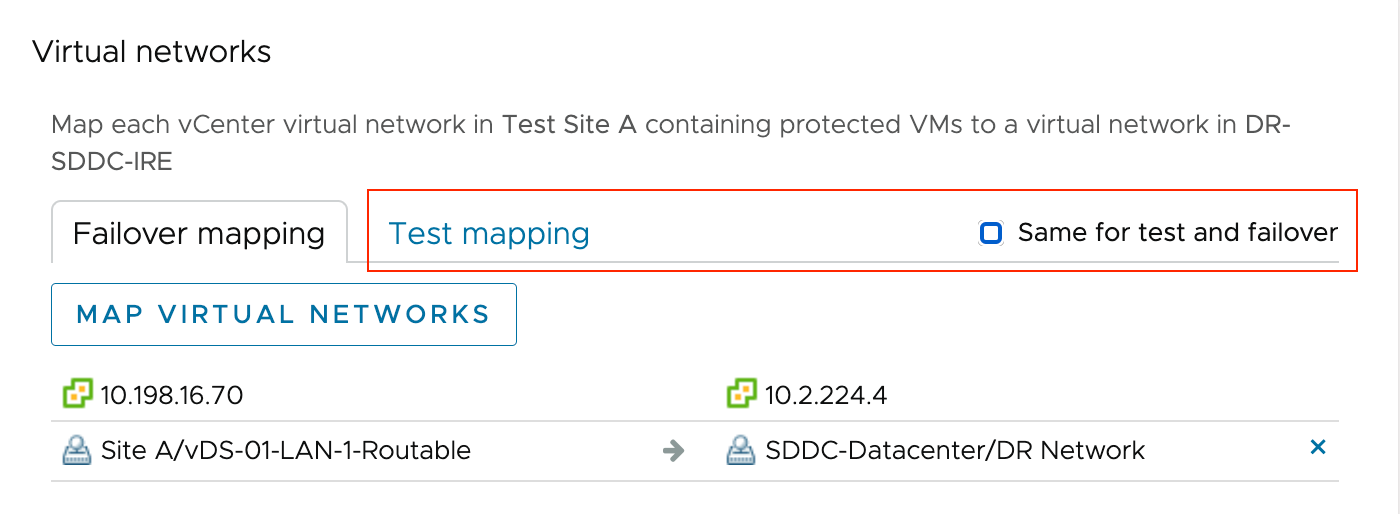
Figure 2 - Test Network Mapping
TASKS
To test Recovery plans with less potential impact on production networking configurations, it is a good practice to define, construct and use additional test network segments during the failover testing. This additional network separation helps with testing many of the Recovery Plan details – like order of recovery – without impacting current production network operations.
Network Mapping for DR
One of the key aspects of the Recovery plan details is the site-to-site mappings for the VMs that are being failed over into the Recovery SDDC. The Orchestrator needs to have the appropriate destination site configuration properties to bring the VM into inventory and power it on. One of these site-to-site mappings addresses the virtual network configuration. It is important to note that the current capabilities of the VMware Cloud DR Recovery plan require a 1:1 mapping from the Protected site network configuration to the Recovery site networks. The VM inventory specified by the Protection Groups used in the Recovery plan will identify which source Protected site networks require a mapping onto unique Recovery site SDDC network segments.
For the VMs brought into inventory in the Recovery SDDC, their corresponding virtual network interfaces will behave according to the network segment to which they are mapped. Considerations for IP resolution follow the configuration chosen. For DHCP IP assignment, the VMs will follow the rules based on the guest VM network settings and the destination network segment used. For static IP assignment, it is important to configure the network segments in the Recovery SDDC appropriately or consider remapping the IP addresses on failover. This remapping is discussed in the next section.
TASKS
When building a Recovery plan, ensure the desired network segments are already defined in the Recovery SDDC for production failovers and failover testing. To complete the plan definition, you must enter all the 1:1 virtual network mapping.
Verify, through testing, that the VMs fail over to the Recovery SDDC and acquire IP addresses as desired – either through DHCP methods or static IP / remapping rules.
IP Remapping Considerations
When failing VMs over from the Protected (production) Site to the Recovery Site (SDDC), the Orchestrator can follow instructions in the Recovery Plan and modify / remap the static IPs of the VMs during the inventory configuration step. This is useful when the VMs want or need to use different IPs running in the DR site.
The specifics of setting up IP mapping rules are covered in the IP Address Mapping documentation.
TASKS
Determine which workloads need their IPs changed when running on the network segments defined in the Recovery Site (SDDC). Verify that the IP configuration is supported (refer to documentation) and that appropriate rules for individual IPs or IP ranges are defined. Remember that Recovery plans can have different mapping rules for failover vs. testing.
Ransomware Network Management – Isolation Control
This Ransomware Recovery features layered on top of the VMware Cloud DR solution provides the capability to control the configuration of the NSX Advanced Firewall rules easily and Compute Group Inventory settings when running or testing Recovery Plans that have been configured for ransomware functionality.
During the recovery of a VM in ransomware recovery, the network mappings defined in the Recovery Plan will be applied to the VM in addition to the Advanced Firewall settings that are part of the Ransomware Recovery configuration. This means that once a Recovery Plan starts, the NSX Advanced Firewall (NSX Distributed Firewall) rules will be constructed in the SDDC configuration. The rules will be removed when there are no more active plans running ransomware recovery.
As VMs are transitioned in the guided workflow from the backup stage (recovery points in the Cloud File System) to the validation stage (VMs in the SDDC inventory), they will also be added to the appropriate Compute Group inventory definitions applied to the firewall rules.
TASKS
When running Recovery Plans for ransomware recovery or ransomware test, it is helpful to review the NSX Network and Security settings in the VMC SDDC details view for the Security – Distributed Firewall rules and the Inventory – Groups – Compute Groups membership to understand better how the “push-button” network isolation capabilities are being implemented. For more information about this feature, refer to the product documentation here: Network Isolation Levels
With a basic understanding of how VMware Ransomware Recovery utilizes Distributed Firewall rules and Compute Group inventories, it is also possible to extend the network isolation choices to include custom isolation settings for your particular Recovery site as defined here: Create a Custom Network Isolation Level
Glossary of Terms
Protected Site
- The Protected Site is the source of the production VM workloads from virtualized environments that are running in either on-premises VMware (vSphere/vCenter) sites, VMware Cloud on AWS SDDCs, or in Google Cloud VMware Engine (GCVE) configured sites.
Recovery Site
- The Recovery Site is the destination of the disaster recovery failover, or the remediation environment used for a ransomware recovery task. Either way, the Recovery Site is hosted in VMware Cloud on AWS.
Scale-out Cloud File System (SCFS)
- The SCFS – also called Cloud File System - is the cloud-based repository of recovery points replicated from VM workload snapshots at the protected sites.
DRaaS Connector (DRC)
- The DRC is the OVA appliance that is user-installed into each Protected Site to enable the snapshot and replication of VM data to the Cloud File System under the control of policies defined in the VMware Cloud DR Orchestrator.
Software Defined Data Center (SDDC)
- The SDDC is the collection of VMware Cloud on AWS components that make up the cloud-based virtualized data center environment. The SDDC includes the hosts (vSphere/ESXi), the management service (vCenter), datastore storage (vSAN), and virtual networking (NSX-T).
Next-Gen Anti-Virus (NGAV)
- NGAV encompasses the full suite of malware tools that provide vulnerability analysis for the operating system and applications, static file-based malware signature scanning and behavior analysis of running workloads to identify potential file-less attacks.
Isolated Recovery Environment (IRE)
- The IRE is a special-purpose SDDC constructed for the tasks associated with recovery operations after a ransomware attack. In addition to the basic elements of the SDDC, the IRE also has the capabilities of providing NGAV resources (Carbon Black) and Network Isolation control (NSX Advanced Firewall) built into the UI of the VMware Cloud DR Orchestrator.
Protection Group (PG)
- The PG is the policy defined in the VMware Cloud DR Orchestrator that controls the desired VM inventory, snapshot type, schedule frequency, and data retention period of the VM snapshot methods applied at each Protected Site.
Recovery Plan
- The Recovery Plan can be considered as the online run book definition captured within the VMware Cloud DR Orchestrator inventory that specifies the details of the scope (e.g., sites and PGs), the mappings between the sites – including virtual network and IP re-mapping rules, the sequence of steps to follow for DR, and any additional plan configuration settings (e.g., ransomware and alerts).
Summary and Additional Resources
VMware Cloud DR provides a robust yet simple-to-manage solution for improving your IT organization's disaster readiness, including recovery from ransomware attacks. Proper setup, configuration, and testing of the networking details of the production data center site and the cloud-based DR site are critical for an effective solution. This field guide has covered most of the basic areas of consideration, from setting up the solution to connecting to the recovery site deployed in VMware Cloud on AWS to run application workloads.
A broad range of additional resources is available from VMware that cover networking of your virtualized environments, whether on-premises or in VMware Cloud on AWS. Many, but not all, of these have been referenced within this field guide to help manage the networking for this disaster recovery solution.
Specific best practices will vary based on how the solution is implemented. Below is a short list of several online resources that could help with the topic of disaster recovery networking.
VMware product documentation:
- https://docs.vmware.com/en/VMware-Cloud-on-AWS/services/com.vmware.vmc-aws-networking-security/GUID-0CD747E8-143D-476C-BE17-7DB991B32D37.html
- https://docs.vmware.com/en/VMware-Cloud-on-AWS/services/vmc-on-aws-networking-security.pdf
- https://docs.vmware.com/en/VMware-HCX/4.5/hcx-user-guide/GUID-E1F066D9-0AA5-4FE1-B3F4-98309C6801AA.html
Onboarding portals:
Tech Zone:
AWS for VMC topics:
- https://aws.amazon.com/blogs/apn/connectivity-options-for-vmware-cloud-on-aws-software-defined-data-centers/
- https://pages.awscloud.com/rs/112-TZM-766/images/2021_VW_s21e01-MIG_Slide-Deck.pdf
Other potentially useful sites: