
VMware Cloud on AWS Evaluation Guide
Introduction
The purpose of this guide is to support a self-guided evaluation of VMware Cloud on AWS. This guide should allow customers to walk through the different features and offerings in the VMware Cloud on AWS service, and allow them to configure and test each one.
Intended Audience
This guide is intended for customers who wish to evaluate VMware Cloud on AWS. Although the majority of the VMware Cloud on AWS features are found in both the single-host offering and the multi-host offerings, this guide was created using a single-host environment and as such, will have several variances to the larger offering based on resources, high-availability, etc.
Assumptions
This guide assumes that you have already received access to VMware Cloud on AWS, created with a MyVMware account, and have added an “Organization”. Details on this process can be found in the Getting Started Guide.
User Interface Walkthrough
Once you have created a VMware Cloud on AWS account and created an ‘Organization’, it is time to explore the user interface (UI). The main UI for all VMware Cloud Services is known as the Cloud Console. This is also where other information is located, such as Organization based management, billing and subscription access, support, and individual user account access.
Cloud Console Walkthrough
The Cloud Console can be accessed by login on to https://console.cloud.vmware.com and there are a number of tabs categorizing different functionality available within the VMware Cloud Services.
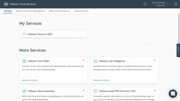
Services
The Cloud Console Services tab shows what you already have access to, like VMware Cloud on AWS, and other services you have the ability to request for use. Each tile can be interacted with, allowing you to access the service or to request access to the services.
Identity & Access Management
The Identity & Access Management tab is where user and group permissions are configured. This area can also be used to invite new users and remove users from the system.
Billing & Subscriptions
The Billing & Subscriptions tab is used for billing and payment information. Current costs, card payments and credits can all be shown in this area.
Support Center
The Support Center tab can be used to help find documentation or log VMware support requests. These requests are linked to a VMware ID will be required to use this feature.
VMware Cloud on AWS Walkthrough
There are two ways to access the VMware Cloud on AWS service.
- Under 'My Services' on the main VMware Cloud Console, click 'VMware Cloud on AWS'
- From anywhere within the service, click on the 9 box icon in the top right of the UI, then select 'VMware Cloud on AWS'
Once on the main VMware Cloud on AWS UI, you will find five main tabs, SDDCs, Subscriptions, Activity Log, Tools and Development Center.
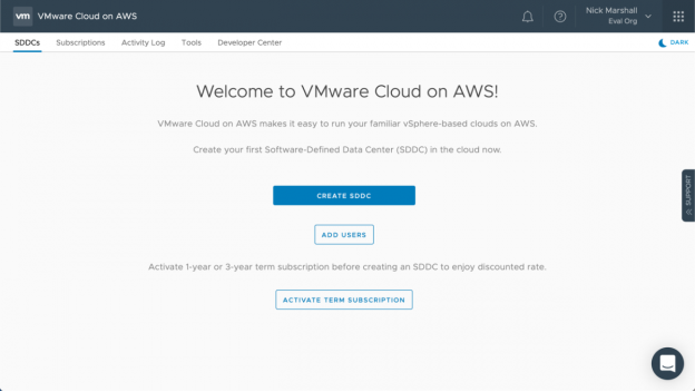
SDDCs
The SDDCs tab shows all of the SDDCs deployed in the organization. For each SDDC deployed some basic information is shown, including, Name, Region, Status and Hardware Allocation. Additionally, there are links for more details and operations that can be performed on the SDDC.
Subscriptions
The Subscriptions tab shows the existing subscriptions that are active for the organization. A subscription is used to pre-pay for hardware at a reduced cost compared to using VMware Cloud on AWS in an on-demand manor.
Activity Log
The Activity Log tab shows a list of the recent tasks that have been performed against all SDDCs within the organization. The task details include: type, time, SDDC, username and associated event.
Tools
The Tools tab give easy access to tools, such as the Content Onboarding Assistant, the DCLI bundle and the vCenter Cloud Gateway. The tools are designed to make using the VMware Cloud on AWS service easier.
Developer Center
The Developer Center tab provides a range of information and downloads to help learn the automation and integration development options available. There are code samples, an API Explorer and other tools to quickly get you up to speed.
SDDC Deployment
Now that we have become familiar with the Cloud Console UI, the next step is to deploy a new Software-Defined Data Center (SDDC). We will walk through the steps it takes to deploy an SDDC and then thoroughly test out the features is contains. For this evaluation, we will be configuring a single-host SDDC, however this can be expanded later to accommodate production workloads.
SDDC Properties
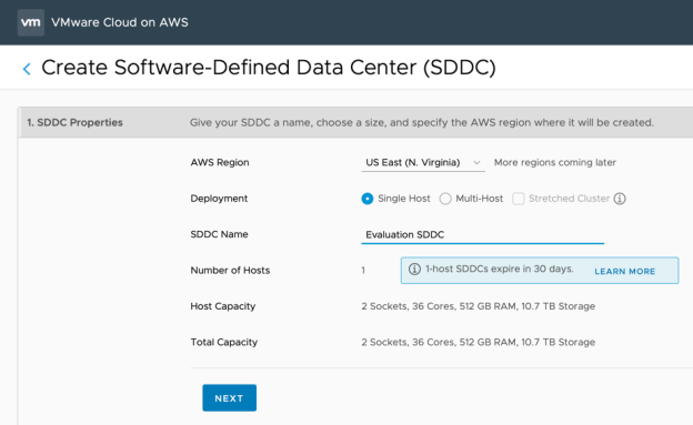
- After logging onto the VMware Cloud Console and selecting VMware Cloud on AWS, click CREATE SDDC from the SDDCs tab.
- The Create SDDC dialog box will appear. Select the AWS Region where you wish to deploy your SDDC.
- For this evaluation, leave the Deployment type as Single Host.
- For a Stretched Cluster deployment, choose “Multi-Host” and check the box for Stretched Cluster. If you wish to evaluate Stretched Clusters, this should be selected here as existing SDDCs cannot be changed into Stretched Clusters
- Choose a name for your SDDC and then click NEXT
Connect to AWS
SDDC deployments are required to connect to an AWS account, regardless of whether the you intend to leverage AWS Services with the VMware SDDC service or not. With single host deployments evaluations, you have the option to skip the account association process for up to 14 days after an SDDC has been deployed.
- Leave the option as "Skip for now" and click NEXT.
The SDDCs tab, you will see reminders of how many days are remaining before an AWS account has to be connected. The AWS Account Linking section details how to configure this once your SDDC has been provisioned.
Configure Network
In order to interact between your VPC and on-premises environment, you must ensure that the management and compute networks in VMware Cloud on AWS do not overlap subnets in either location.
- Input the desired subnet for the Management network.
- Note: The default subnet of 10.2.0.0/16 will be used if one is not entered.
- Select ‘DEPLOY SDDC’
The SDDC will begin to deploy and should be ready for use in roughly two hours.
Accessing vCenter
Once the SDDC finishes deploying, the next step will be to establish connectivity to the vCenter Server. The easiest way to do this is by creating a firewall rule. This firewall rule will allow network connectivity to the public IP assigned to the vCenter Server.
vCenter Firewall Rule Management
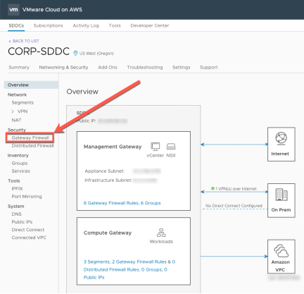
- Open VMware Cloud on AWS from the Cloud Services Console.
- Select 'VIEW DETAILS' for the SDDC in the VMware Cloud on AWS UI
- Click on the ‘Network & Security’ tab
- Beneath the ‘Security’ section, select ‘Gateway Firewall’
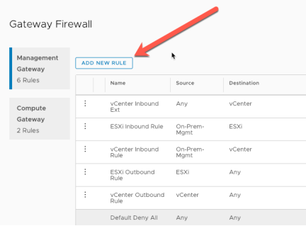
- Ensure ‘Management Gateway’ is highlighted, click ‘ADD NEW RULE'
- Create a firewall rule with the following settings:
- Enter a valid name, example: vCenter Inbound Rule
- Source = any
- Destination = vCenter
- Services = HTTPS (TCP 443)
- Click PUBLISH
Alternatively, the vCenter Server can also be accessed by configuring a VPN between your on-Premises location and the VMware Cloud on AWS environment or by establishing a Direct Connect through Amazon AWS itself.
Logging into vCenter Server
Each deployed vCenter will have a set of default administrator credentials to be used until an identity source is added or additional users have been added. Use the default credentials to login to vCenter.
- Open VMware Cloud on AWS from the Cloud Services Console.
- Click 'OPEN VCENTER' for the SDDC in the VMware Cloud on AWS UI
- After the 'Open Access to vCenter' dialogue box appears select 'SHOW VCENTER CREDENTIALS'
- Use the 'Copy password' to clipboard' button and select 'OPEN VCENTER'
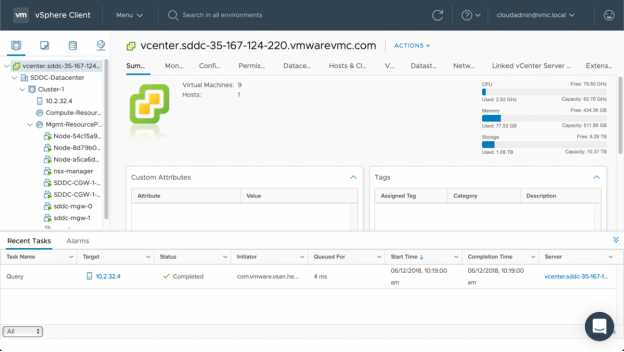
- The vCenter Server UI will now load in a new window.
- Fill the username 'cloudadmin@vmc.local' and paste the 'Password’ into the password textbox on the vSphere Client login page.
- The vSphere Client will load and present a very familiar view for those that use vSphere in their on-premises environment.
 Feedback
AWS Account Linking
linking to AWS during the SDDC deployment, you may follow the steps here to establish your account’s connection to AWS. If you linked an account to AWS during deployment, you may skip this section.
Connect to AWS
- On the main screen of the SDDC, click ‘CONNECT TO AWS ACCOUNT’

- Login to AWS with your username and password
- Check ‘I acknowledge that AWS CloudFormation might create IAM resources
’
- Click ‘Create’
- Return to the VMware Cloud on AWS SDDC Deploy tab, waiting for the account linking process to complete
- Once you see the ‘Congratulations!’ message, click ‘Next’
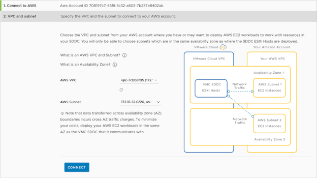
VPC and Subnet
- From the VPC drop down, select the desired VPC
- From the Subnet drop down, select the desired subnet
- Click ‘Next’
Note: To avoid cross AZ traffic charges, we recommend ensuring that the SDDC deploys into the same availability zone as the subnet chosen here.
Adding Virtual Machine Networks
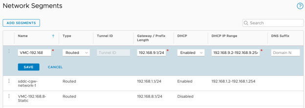
Just like on-premises, Virtual Machines inside the cloud SDDC need a network to connect to so they can communicate between themselves and other network services. Within VMware Cloud on AWS, those networks are provided by NSX-T Logical Switches and are called Network Segments. By default, a single Network Segment is created, named sddc-cgw-network-1 and is connected to the Compute Gateway. Create two new Network Segments, using the Cloud Console:
- Open VMware Cloud on AWS from the Cloud Services Console.
- Select 'VIEW DETAILS' for the SDDC in the VMware Cloud on AWS UI
- Click on the ‘Network & Security’ tab
- Beneath the ‘Network’ section, select ‘Segments’
- Click ‘ADD SEGMENTS'
- Create a segment with the following settings:
- Name = VMC-192.168.8-Static
- Type = Routed
- Gateway = 192.168.8.1/24
- DHCP = Disabled
- Click 'SAVE'
- Once Again, click ‘ADD SEGMENTS'
- Create a segment with the following settings:
- Name = VMC-192.168.9-DHCP
- Type = Routed
- Gateway = 192.168.9.1/24
- DHCP = Enabled
- DHCP IP Range = 192.168.9.2-192.168.9-254
- DNS Suffix can be left blank
- Click 'SAVE'
Hybrid Cloud
Enabling a Hybrid Cloud using Hybrid linked mode gives users the ability to login to their cloud SDDC with their on-premises credentials, view and manage both on-premises and cloud resources from a single pane of glass, and migrate workloads from on-premises to the cloud.
VPN Configuration
A Management Gateway VPN enables easy connectivity from on-premises environment to your SDDC for functionality like Enhanced Linked Mode. Similarly, you can also configure a Compute Gateway VPN for workload mobility. This process is optional and is not required for standalone / non-hybrid environments.
Either IPSec or L2TP VPN tunnels can be configured. Within this guide, we'll step you through the IPSec configuration.
Within the SDDC, click the ‘Network & Security’ tab
Beneath the ‘Network’ section, expand ‘VPN’, click ‘Policy Based’
- Click ‘Add VPN’
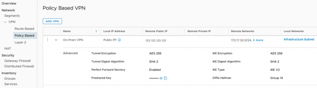
- Give the VPN a name, such as: Management VPN
- For ‘Local IP Address’, select the appropriate public IP from the drop-down options
- For ‘Remote Public IP’, enter the public IP for the on-premises VPN
- For ‘Remote Networks’, add the on-premises network subnet(s) that will communicate on the VPN
- For ‘Local Networks’, choose the SDDC based network which will communicate over the VPN. Example: Infrastructure Subnet for Hybrid Linked Mode
- Select the Encryption, Perfect Forward Secrecy, Diffie Hellman, IKE, and SHA details that match your on-premises VPN settings
- Enter the Pre-Shared Key from your on-premises VPN configuration
- Click ‘SAVE’
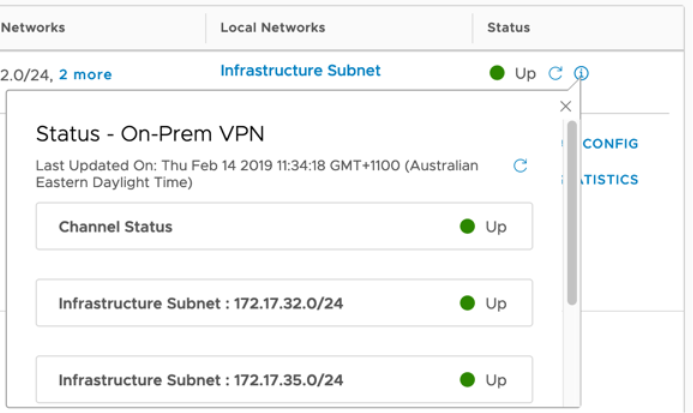
Once the VPN configuration has been set up on both the local on-premises endpoint and also with the VMC SDDC console, the status icon should change to green with the word "up" next to it. Clicking on the (i) icon can provide more information including any troubleshooting help you may require.
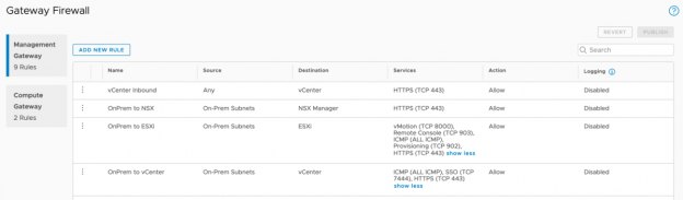
Firewall Rule Management
By default, VMC allows the cloud SDDC vCenter and ESX outbound access to any destination, however all inbound connections are blocked at the management gateway firewall.
To enable Hybrid Linked Mode, you will need to establish a new IP group for your on premises subnets and then allow those subnets through the firewall on specific ports. This can be done within the firewall creation rule itself, or in the Inventory Groups section.
- Within the SDDC, click on the ‘Network & Security’ tab
- Beneath the ‘Inventory’ section, ensure ‘Management Groups’ is selected and then click 'ADD GROUP'
- Name the group 'On-Prem Subnets' and add the IP subnets that you have configured in the 'Remote Networks' section of your VPN connection(s)
- Click 'SAVE'
Now that the Group is created, you can create firewall rules based on the group.
- Still within the SDDC Networking and Security tab, select Gateway Firewall
- In the Management Gateway section, click 'ADD NEW RULE'
- Enter a valid name, example: On-Prem to vCenter
- Click ‘Set Source’, under 'User Defined Groups', select 'On-Prem Subnets' , click ‘SAVE’
- Click ‘Set Destination’, click vCenter’ and click 'SAVE'
- Choose each of the available services 'HTTPS', 'SSO' and 'ICMP'
- Click the 'Publish" button at the top right of the firewall rule list.
Once the On-Prem to vCenter rule is created, the next step is to create additional rules that all access from the on premises environment to the ESXi hosts and NSX manager:
- Name: OnPrem to ESX
- Source: On-Prem Subnets
- Destination: ESXi
- Sources: vMotion, Remote Console, ICMP, Provisioning, HTTPS
- Name: OnPrem to NSX
- Source: On-Prem Subnets
- Destination: ESXi
- Sources: HTTPS
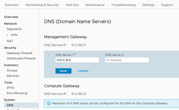
DNS Settings
To ensure that FQDNs can be resolved from the cloud SDDC, the DNS resolution needs to be updated.
- From within the SDDC select the Networking & Security tab.
- Under 'System' click 'DNS'
- Remove the existing DNS Server entries
- Set DNS Server 1 (and optionally DNS Server 2) to be your on-premises DNS server(s) (usually an Active Directory Domain Controller).
Hybrid Linked Mode
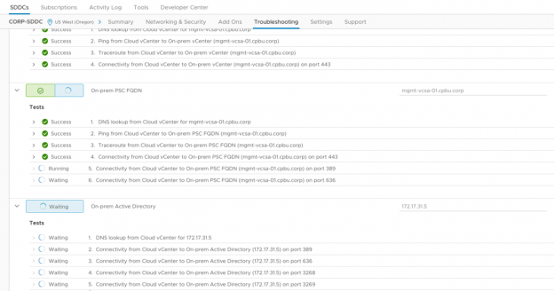
Connectivity Testing
After the VPN, firewall rules and DNS settings are configured, it's a good idea to run through the Hybrid Linked Mode troubleshooting tests to ensure everything is working before deploying the Cloud Gateway Appliance.
- Within the SDDC, click on the 'Troubleshooting' tab and ensure that the 'Hybrid Link Mode' use case is selected.
- Put the correct IP or FQDN to the respective dialog boxes and click 'RUN ALL TESTS'.
- If any tests fail, ensure you have configured all of the perviously mentioned VPN, firewall rule and DNS settings.
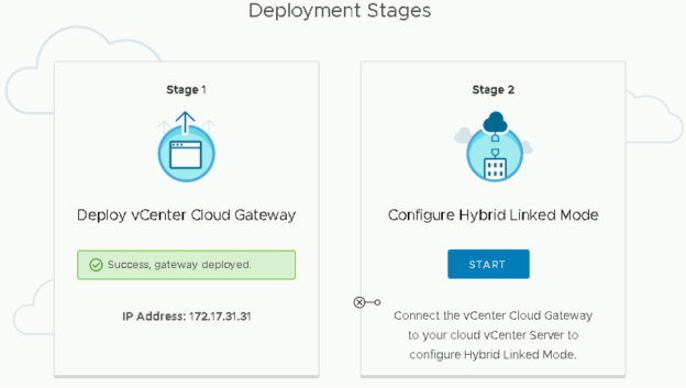
Installing vCenter Cloud Gateway
After verifying that the connectivity between your on-premises data center and the VMware Cloud on AWS SDDC, the next step is to download and install vCenter Cloud Gateway. vCenter Cloud Gateway links to your local, on-premises vCenter Servers, and then acts as a proxy to the cloud SDDC.
- Navigate to the 'Tools' tab in VMware Cloud on AWS console
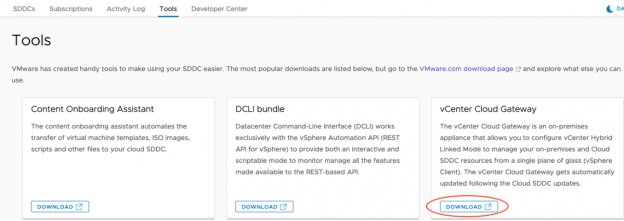
- Download the vCenter Cloud Gateway ISO file
- Mount the ISO file and run the installer (\ui-installer\wind32\installer.exe)
- Click 'GET STARTED' on the Welcome screen
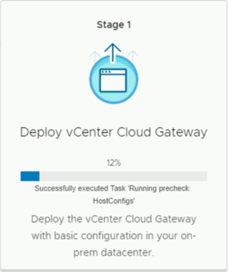
- On the Deployment Stages page, select 'START' under 'Deploy vCenter Cloud Gateway' to start the appliance deployment.
- On stage 1, accept the EULA, and click 'NEXT'
- Enter the vCenter (or ESXi host) that you wish to deploy the new appliance to, along with the target's username and password, then click 'NEXT'
- If you have an untrusted SSL certificate installed, you will be required to click 'YES' to continue
- On the 'Select folder' section of the installer, use the dropdown tree to select where you would like the vCenter Cloud Gateway appliance to be deployed and then click 'NEXT'
- Select the correct cluster or host that you wish to use for the new appliance and click 'NEXT'
- The next screen allows you to customize the name and specify a root password. After entering these details, click 'NEXT'
- On the 'Select datastore' section, choose the datastore allocation and enable Thin Disk Mode if appropriate. Click 'NEXT' to continue
- Choose the correct Network (portgroup), IP version, IP assignment, FQDN, IP address, Subnet mask, gateway and DNS settings. Click 'NEXT'
- Within the 'Appliance configuration' section, ensure to choose an appropriate NTP server, preferably the same NTP server that your existing vCenter Server(s) are pointing to. Click 'NEXT' to continue
- Enter your SSO (Single Sign-On) details for the Platform Services Controller, HTTPS port, SSO domain, SSO username and SSO password. Click 'NEXT' to continue to the final configuration section. If you have an untrusted SSL certificate you will be required to click 'YES' to accept and continue.
- Optionally, enter the details to join the vCenter Cloud Gateway appliance to your Active Directory with a computer account. Click 'FINISH' and the appliance OVF will be deployed to your environment.
Configuring Hybrid Linked Mode
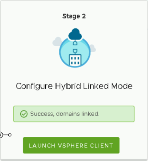
Once the vCenter Cloud Gateway appliance is deployed, the next, and final part of the process is to configure the appliance.
- On the 'Deployment Stages' screen of the installer, click the 'START' button under 'Stage 2'
- Click 'NEXT' on the 'What is Hybrid Linked Mode?' section
- In the 'Hybrid Linked Mode' section, enter the FQDN for your VMC based vCenter server.
- EG: vcenter.sddc-123-123-123-123.vmwarevmc.com
- Additionally, a username and password for a VMC based Administrator account.
- Select a local AD domain, or on-premises SSO domain, and group that you wish to grant access to VMC. This enables the single logon for views and operations between you local on-premises vCenter and the offsite VMC based SDDC cloud.
- Click 'FINISH' to initiate the connection between vCenter Servers and click 'YES' if you have untrusted SSL certificates in your environment.
- After the domains have been successfully linked, you can log into the new vCenter Cloud Gateway appliance with an account that is in the group entered in Step-5. You will then see you local on-premises vCenter Servers, as well as the VMware Cloud on AWS SDDC vCenter Server.
Integrating with AWS Services
Workload integrations with AWS services is one of the most appealing benefits for customers who already are running workloads in AWS. Here you will walk through steps to enable communication between the VMware stack and AWS service.
SDDC to AWS service Network Configuration
Enable Inbound ENI Traffic on the Compute Network
- Within the SDDC, click on the ‘Network & Security’ tab
- Beneath the ‘Security’ section, select ‘Gateway Firewall, then select the Compute Gateway tab’
- Click ‘Add Rule’
- Create a firewall rule with the following settings:
- Enter a valid name, example: ENI – Inbound
- Click ‘Set Source’, checkmark ‘Any’, click ‘SAVE’
- Click ‘Set Destination’, checkmark ‘Connected VPC Prefixes’, click ‘Save’
- Click ‘Set-Service’ section, select ‘Any’, click ‘Save’ o For ‘Applied To’, remove ‘All Uplinks’, and add ‘VPC Interface’
- Click ‘PUBLISH’
Enable Outbound ENI Traffic on the Compute Network
- Within the SDDC, click on the ‘Network & Security’ tab
- Beneath the ‘Security’ section, select ‘Gateway Firewall, then select the Compute Gateway tab’
- Click ‘Add Rule’
- Create a firewall rule with the following settings:
- Enter a valid name, example: ENI – Outbound
- Click ‘Set Source, checkmark ‘Connected VPC Prefixes’, click ‘Save’
- Click ‘Set Destination’, checkmark ‘Any’, click ‘Save’
- Click ‘Set-Service’ section, select ‘Any’, click ‘Save’
- For ‘Applied To’, remove ‘All Uplinks’, and add ‘VPC Interface’
- Click ‘PUBLISH’
Enable Cross-ENI Traffic on the AWS Security Group
You have configured inbound and outbound traffic for AWS services across the ENI from the SDDC-side of the environment. Now, you must also allow traffic into and out of the AWS VPC using the AWS Security Groups.
- Open a new browser tab and login to your AWS account at:
- Click on ‘EC2’
- In the left-pane, scroll down and click on ‘Security Groups’
- Select the Security Group for the associated VPC that is connected to the SDDC.
- Select the ‘Inbound’ tab
- Click the ‘Edit’ button
- Click ‘Add Rule’
- Under ‘Type’, select ‘All traffic’
- Under ‘Source’, select ‘Custom’ from the drop-down box and enter ‘192.168.0.0/16’ in the corresponding textbox
- Under ‘Description’, type ‘VM Traffic’
- Click ‘Save
- Select the ‘Outbound’ tab
- Click ‘Edit’
- Click ‘Add Rule’
- Under ‘Type’, select ‘All traffic’
- Under ‘Destination’, select ‘Custom’ from the drop-down box and enter ‘192.168.0.0/16’ in the corresponding textbox
- Under ‘Description’, type ‘AWS Traffic’
- Click ‘Save'
Enable S3 Traffic Across the ENI
Once we’ve enabled communications across the Elastic Network Interface, we can enable an S3 Endpoint and allow all S3 traffic to navigate over the ENI rather than out the Internet Gateway (IGW).
- Within the AWS Console, Select ‘VPC’
- Click on ‘EC2’
- In the left-pane, find and click ‘Endpoints’
- Click ‘Create Endpoint’
- Under Service category, click ‘AWS Services’
- Find and select ‘com.amazonaws.us-[your region].s3’
- In the VPC combo-box, select the VPC linked to the SDDC
- Select the corresponding route table for the endpoint
- Find and click ‘Create Endpoint’
Integrating Content Library with Amazon S3
Adding a Content Library allows users to quickly and easily begin deploying templates into their cloud SDDC.
This task will walk you through the steps of adding a pre-created Content Library, which should only be used with the Evaluation Guide.
- Login to your SDDC’s vSphere Client
- Click ‘Menu’
- Select ‘Content Libraries’
- Click the ‘Add’ symbol
- Name the Content Library ‘vExpert-Content-Library’
- Click ‘Next’
- Select ‘Subscribed content library’
- Paste the following URL into the ‘Subscription URL’:
- https://s3-us-west-2.amazonaws.com/vexpert-content- library/lib.json
- For the ‘Download Content’ entry, select ‘Immediately’
- Click ‘NEXT’
- Accept the SSL thumbprint of the certificate by clicking ‘YES’
- Select ‘WorkloadDatastore’
- Click ‘NEXT’
- Click ‘FINISH’
Virtual Machine to EC2 Instance Networking
Many customers are excited about the ability to allow EC2 instances to communicate with VMware virtual machines. This capability provides customers with the ability to choose which applications run on each technology. In this task we will deploy an EC2 instance that we will use to ping a VM workload with its private IP, and vice versa.
Build an EC2 Instance
- From within the AWS Console, select ‘EC2’
- Click ‘Instances’
- Click ‘Launch Instance’
- Find and select “Microsoft Windows Server 2016 Base’
- Select ‘t2.micro – Free tier eligible’
- Click ‘Next: Configure Instance Details’
- Under ‘Network’, select the VPC that is connected to your SDDC
- Under ‘Subnet’, select the subnet of the SDDC
- Under ‘Auto-assign Public IP’, select ‘Enable’
- Click ‘Next: Add Storage’
- Click ‘Next: Add Tags’
- Click ‘Add Tag’
- Configure the following values:
- Key = ‘Name’
- Value = ‘Test EC2 to VM’
- Click ‘Next: Configure Security Group’
- Choose ‘Select an existing security group’
- Select the security group configured in the previous steps
- Note: We will need to add additional rules after the EC2 instance is deployed
- Select ‘Review and Launch’
- Select ‘Launch’
- Create a new Key Pair
- Give the new key pair a name
- Click ‘Download Key Pair’
- Click ‘Launch Instances’
While we wait roughly 5 minutes for the instance to be in a running state, we can go ahead and edit the security group configuration.
Edit the Security Group
- Click ‘View Instances’
- Scroll down in the left-pane and click on ‘Security Groups’
- Select the corresponding Security Group and click the ‘Inbound’ tab
- Click ‘Edit’
- Click ‘Add Rule’
- Configure the rule as follows:
- Type = ‘RDP’
- Source = ‘0.0.0.0/0’ (or your public IP if you choose) o Description = ‘RDP to EC2 Test Instance’
- Click ‘Save’
- In the left-pane, find and select ‘Instances’
- Select the instance you previously deployed and click ‘Connect’
- Download the Remote Desktop File to your local machine
- Click ‘Get Password’
- Click ‘Choose File’ next to ‘Key Pair Path’ and select the Key Pair you created when deploying this instance
- Click ‘Decrypt Password'
- Copy the password and open an RDP session to your EC2 instance using the Remote Desktop File
Check traffic flow
- Before we begin working in the EC2 instance, login to the SDDC’s vSphere Client, select the ‘Server-2012-01’ VM and take note of its IP Address from the VM summary page
- Note: If the VM is not powered on, power it on at this point and wait for the IP Address to populate
- Return to the RDP session and open the command prompt
- Ping the IP address of ‘Server-2012-01’
You are now pinging an internal IP address located in the VMware Cloud on AWS account from an internal IP address of an EC2 instance running in your own AWS account.
Remove the EC2 Instance
If you wish to terminate the EC2 instance to avoid hourly charges, close the RDP session and return to the AWS Console
- Select your EC2 Instance and click ‘Actions’
- Maneuver to ‘Instant State’ > ‘Terminate’
- The EC2 Instance will power off and be deleted
Virtual Machine to RDS Database Integration
Just like customers are able to use EC2 Instances with VMware virtual machines, our virtual machines can take advantage of the Relational Database Service (RDS) and connect to databases in AWS.
Create a new Virtual Machine
- Login to your Cloud SDDC vCenter
- Click ‘Menu’ and select ‘Content Libraries’
- Select the ‘vExpert-Content-Library’ and click ‘Templates’
- Right-Click ‘Lychee-Automated-Demo’ and click ‘New VM from This Template’
- Name your VM ‘Frontend-With-RDS’
- Expand ‘SDDC-Datacenter’
- Select the ‘Workloads’ folder
- Click ‘Next’
- Expand ‘Cluster-1’, select ‘Compute-ResourcePool’ and click ‘Next’
- Click ‘Next’ on the ‘Review Details’ page
- Select the ‘WorkloadDatastore’
- Select the ‘sddc-cgw-network-1’ Destination Network
- Click ‘Next’
- Click ‘Finish to deploy the VM
- Once the VM is deployed, Power-on the VM
Create an RDS MySQL Instance
- Open the AWS Console
- Click ‘Services’ and select ‘RDS’
- Click ‘Get Started Now’
- Select ‘MySQL
- Click ‘Next’
- Select ‘Dev/Test – MySQL’, then click ‘Next’
- Scroll down to ‘DB instance class’
- Select ‘db.t2.micro’
- Scroll down to ‘Settings’
- Configure the following settings:
- DB instance identifier = ‘vmc’
- Master username = ‘vmcadmin’ o Master password = ‘VMware1!’
- Click ‘Next’
- In ‘Network & Security’, select the VPC that is connected to your SDDC
- Ensure ‘Public accessibility’ is set to ‘No’
- Select the Availability Zone where you deployed your SDDC
- Choose existing VPC security groups and ensure the Security Group you configured earlier is selected.
- Under ‘Database options’
- Name the database ‘MySQL_VMC’
- Scroll down to ‘Backup’
- Change the ‘Backup retention period’ to ‘0 days’
- Scroll to the bottom and click ‘Launch DB instance’
- Click ‘View DB instance details’
- Refresh the page periodically until ‘DB instance status’ shows ‘available’
- Scroll down until you see the ‘Endpoint’ address
- Keep this tab available and go back to vCenter Server
Launch the Frontend Virtual Machine
- Click on the ‘Frontend-With-RDS’ VM
- Click ‘Launch Web Console’
- Select the new tab with the web console and login to the ubuntu VM
- Login with credentials:
- User: brian
- Password: VMw@re123
- Open Firefox and go to ‘127.0.0.1’
- Here our web application is asking for the database credentials for our RDS instance.
- RDS Endpoint Address
- Username = ‘vmcadmin’
- Password = ‘VMware1!’
- Database name = ‘MySQL_VMC’
- Click ‘Connect'
- Enter the following credentials:
- User = ‘vmc’
- password = ‘vmc’
- Click ‘Create Login’
You’ve now successfully connected a front-end VM to and RDS database. To test out this app, you can either request a public IP, add an http firewall rule, and NAT rule to this VM, or you can move on to the next section on using Application Load balancers and apply the same steps there, with the private IP of this VM.
When you are finished, select your ‘vmc’ RDS instance and click ‘Instance Actions’ and select ‘Delete’ to avoid additional hourly charges for the instance.
Using Application Load Balancers with Virtual Machines
One of the easiest ways to take advantage of AWS services with webserver virtual machines is the Application Load Balancer (ELBv2). The ELBv2 allows for forwarding HTTP/S traffic to private IP addresses along with pointing to a specific EC2 instance.
Create Front End Web Servers
- Login to your Cloud SDDC vCenter
- Click ‘Menu’ and select ‘Content Libraries’
- Select the ‘vExpert-Content-Library’ and click ‘Templates’
- Right-Click ‘Frontend-Apache-01’ and click ‘New VM from This Template’
- Name your VM ‘Frontend-Apache-01’
- Expand ‘SDDC-Datacenter’
- Select the ‘Workloads’ folder
- Click ‘Next’
- Expand ‘Cluster-1’ and select ‘Compute-ResourcePool’
- Click ‘Next’
- Click ‘Next’ on the ‘Review Details’ page
- Select the ‘WorkloadDatastore’
- Select the ‘sddc-cgw-network-1’ Destination Network
- Click ‘Next’
- Click ‘Finish to deploy the VM
- Once the VM is deployed, Power-on the VM
- Repeat the previous steps for ‘Frontend-Apache-02, 03, and 04’ (03 and 04 are optional)
Create the Target Group
- Login to the AWS Console
- Click ‘Services’ and select ‘EC2’
- In the left-pane, scroll down and select ‘Target Groups’
- Click ‘Create target group’
- Enter the following information:
- ‘Target group name’ = ‘VM-Frontend-TG’
- Protocol = ‘HTTP’
- Port = ‘80’
- Target type = ‘IP’
- VPC = [VPC the SDDC is connected to]
- Click ‘Create’
Create the Load Balancer
- With our new Target Group selected, click the ‘Targets’ tab
- Click ‘Edit’, Select the ‘+’ button
- Under ‘Network’, select ‘Other private IP address’
- Set ‘Availability Zone’ to ‘All’
- Add the IP addresses of the 4 ‘Frontend-Apache-*’ VMs one by one, and click ‘Add to list’
- Click ‘Register'
- In the left-pane scroll down and select ‘Load Balancers’
- Click ‘Create Load Balancer’
- Find ‘Application Load Balancer’ and click ‘Create’
- Name your load balancer ‘VMC-LB’
- Scroll down to ‘Availability Zones’
- Select the VPC that is linked to the SDDC
- Check the checkbox next to ‘Availability Zone’ to select all AZ’s
- Click ‘Next: Configure Security Settings’
- Click ‘Next: Configure Security Groups’
- Click ‘Select an existing security group’
- Choose the Security Group you have configured
- Click ‘Next: Configure Routing’
- Select ‘Existing target group’ next to ‘Target Group’
- Select the ‘VM-Frontend-TG’
- Click ‘Next: Register Targets’
- Click ‘Next: Review’
- Click ‘Create’ Click the hyperlink on the load balancer ‘VMC-LB’ and wait until it is finished provisioning
Add a Security Rule
- While the load balancer is provisioning, in the left-pane, select ‘Security Groups’
- Select your Security Group and select the ‘Inbound’ tab
- Click ‘Edit’
- Click ‘Add Rule’
- Enter the following information:
- Type = ‘HTTP’
- Source = ‘Custom’, ‘0.0.0.0/0, ::/0’
- Description = ‘Load Balancer’
- Click ‘Save’
- Click back to the ‘Load Balancers’ page
- Copy the ‘DNS name’ address from the load balancer basic configuration and paste it in a new tab
You will now see a static webpage with the VM name that is being resolved. Click ‘Refresh’ and watch as the Load Balancer distributes the request between your virtual machines.
When you are finished with this demo, you can delete the load balancer and target groups from your AWS account.
Disaster Recovery
This section walks through the different features and offerings in the VMware Site Recovery service and provides guidance how to configure and test them. The exercises should be completed in the order prescribed for best results. Some exercises have dependencies on previously completed items.
Pre-requisites
This guide assumes that you have already completed the steps related to AWS account linking, network configuration and initial firewall configuration, and therefore have access to a fully functional SDDC. In addition to this there are the following requirements before activating and installing VMware Site Recovery.
Test Virtual Machines
To test the operation of VMware Site Recovery it is recommended to use a few Windows or Linux based virtual machines with a current version of VMware Tools installed.
Network connectivity
There are a couple of different topologies for implementing VMware Site Recovery and some network connectivity requirements are unique to each.
Customer Site to VMware Cloud on AWS
For VMware Site Recovery connectivity, you must have a network connection from the remote site to the SDDC Management Gateway. This connection can either be a VPN or a private VIF. Instructions for how to set this up are available in the documentation.
VMware Cloud on AWS to VMware Cloud on AWS
VMware Site Recovery also supports protecting virtual machines running in an SDDC in one region to be protected to another SDDC in the same or another region. The same connectivity options are supported for this option as well. There are a few differences as far as deployment and operations with this topology, they will be noted in this guide.
Site Recovery Manager Server
When deploying Site Recovery Manager on-premises it must be installed on a Windows server. Before proceeding with this evaluation guide deploy a VM with Windows Server (2016, 2012 64-bit or 2008 R2 64-bit) with a static IP address.
DNS
DNS forward and reverse lookups need to be configured for the IP addresses that will be used for the on-premises Site Recovery Manager (SRM) server and vSphere Replication appliance. If this is being configured between SDDCs this is not required.
Make sure that the remote site firewall allows for DNS requests from the VMware Cloud on AWS Management Gateway private IP address. Without this, DNS forwarding from VMware Cloud on AWS to the remote site will fail.
NTP
All parts of VMware Site Recovery are sensitive to time skew. vCenters and PSCs as well as for the Site Recovery Manager server and vSphere Replication appliance. The VMware Cloud on AWS vCenter, SRM server and vSphere Replication appliance all are configured and enabled for NTP. No user configuration is required for NTP for management components within VMware Cloud on AWS.
Deployment
The steps for deployment of VMware Site Recovery are:
- Activate the Site Recovery Add On
- Install on-premises components (SRM and vSphere Replication)
- Configure VMware Cloud on AWS Firewall
- Pair sites
- Map resources
- Configure placeholder datastores
After these steps are completed VMware Site Recovery is ready to start protecting and recovering VMs.
If deploying VMware Site Recovery between two SDDCs the steps are:
- Activate the Site Recovery Add On in both SDDCs
- Configure VMware Cloud on AWS Firewall
- Pair sites
- Map resources
- Configure placeholder datastores
Recommendation: Use default settings for all components - installation paths, TCP port settings, and so on - wherever possible, to minimize complexity in the evaluation environment. Use consistent naming conventions, usernames, and passwords during evaluation environment deployment.
Recommendation: Use descriptive names for the components such as servers and port groups in a VMware virtualized environment. These names appear in the user interface and VMware Site Recovery history reports. Descriptive names improve the quality of these reports and ease troubleshooting. Use the same naming convention for items such as network port groups at the protected site and the recovery site, as this will simplify inventory mappings.
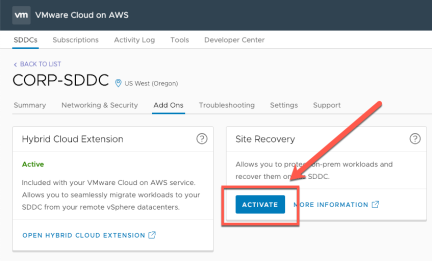
Activating Site Recovery
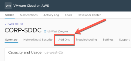
Start by selecting “Add Ons” from the SDDC main menu within the VMware Cloud on AWS console.
Click “Activate”
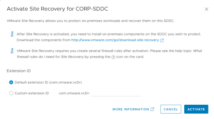
Choose the Default extension ID unless this installation involves more than a single pair of SRM servers. If using the custom extension ID make sure that it exactly matches (case sensitive) the remote site custom extension ID. Click “Activate”
No other user action is required for activation. While the VMware Site Recovery add-on is being activated start downloading and installing the on-premises components.
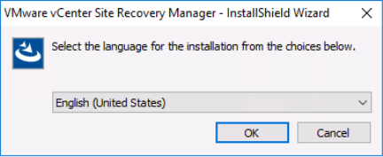
Installing Site Recovery Manager
Run the SRM installer executable
Select the installation language and click “OK”
Click “Next”
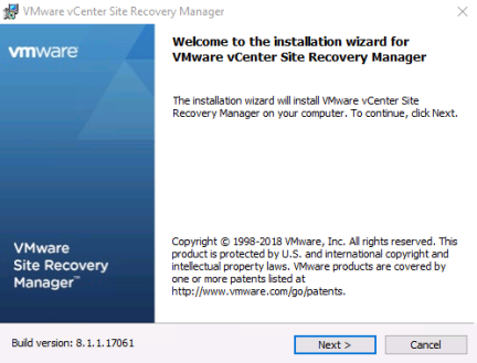
Click “Next” at the VMware Patents dialog
Read the License Agreement and select “I agree”, click “Next”
Confirm that the installation pre-requisites have been completed, click “Next”
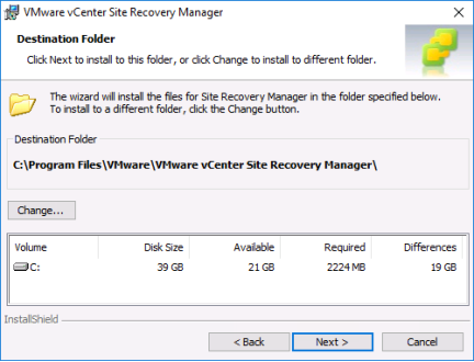
Select the destination folder, click “Next”
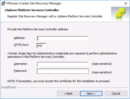
Provide the address (IP address or preferably FQDN) of the on-premises PSC and the SSO credentials to perform administrative operations on the same PSC. Click “Next”
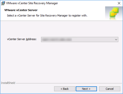
Verify and accept the windows certificate if applicable
Select the appropriate vCenter Server for SRM to register with. Click “Next”
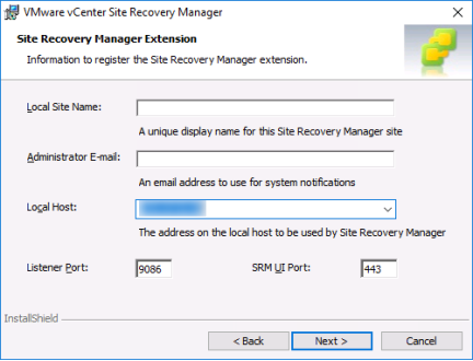
Enter a name for the Local Site, eg. “San Jose”, “Site A”, etc. Enter an email address for system notifications and select the address on the local host to be used for SRM (the default is usually good). We do not recommend changing the listener or SRM UI ports for an evaluation. Click “Next”
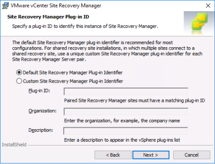
Select the same option and if using the Custom SRM Plug-in Identifier enter the exact same, case sensitive string in the “Plug-in ID” field (type only the text that was entered, not the “com.vmware.vcDr-“ portion.
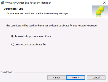
Select the certificate option as appropriate. For the purpose of this evaluation guide we will select “Automatically generate a certificate”. If you have the requirement to use a signed certificate follow the installation directions here. Click “Next”
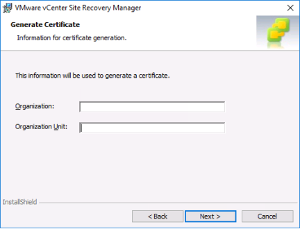
Enter the Organization and Organization Unit for the certificate. Click “Next”
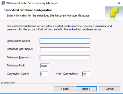
Select “Use the embedded database server”. The embedded database supports the full scale of VMware Site Recovery. If there is a requirement to use an external database follow the guidance in the SRM installation guide.

Enter the following:
Data Source Name (may only contain alphanumeric characters and underscores)
Database User Name (may only contain lower case alphanumeric characters and underscores. You may not use “postres”)
Database Password (may not contain any white spaces, quotation marks, backslashes or extended ASCII characters).
Do not change the database port, connection count or max connections
Make sure to note down the DSN, DB User Name and DB Password. Click “Next”
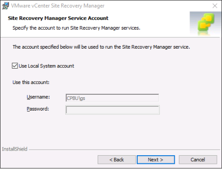
Select the account used for running the SRM service. Unless otherwise required select the default (Local System Account). Click “Next”
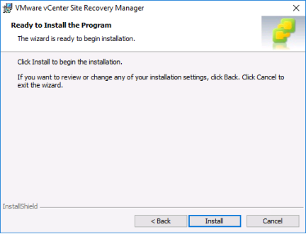
Click “Install”
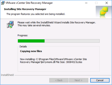
While SRM is installing you can start deploying the vSphere Replication Appliance.
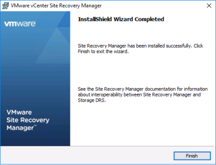
When the installation has finished click “Finish”
Installing vSphere Replication
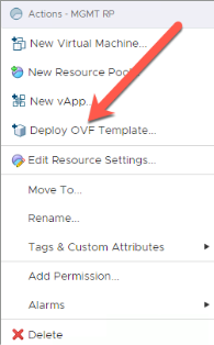
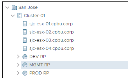
From within the on-premises vCenter, right-click the Cluster or Resource Pool where the appliance will be deployed and select “Deploy OVF Template”
Select “Local File” and “Choose Files”
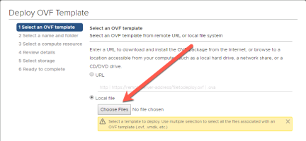
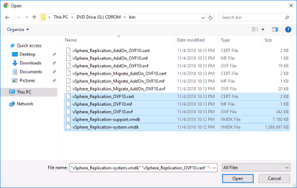
Browse to the CDROM image and the bin folder. Select the following files
• vSphere_Replication_OVF10.cert
• vSphere_Replication_OVF10.mf
• vSphere_Replication_OVF10.ovf
• vSphere_Replication-support.vmdk
• vSphere_Replication-system.vmdk
and click “open” then click “next”
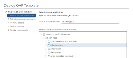
Specify a unique name and target folder for the vSphere Replication Appliance
Select a compute resource
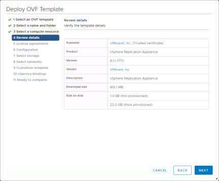
Verify the template details and click “Next”
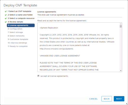
Select the “I accept all license agreements” checkbox. Click “Next”
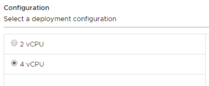
Leave the configuration on 4 vCPU. Click “Next”
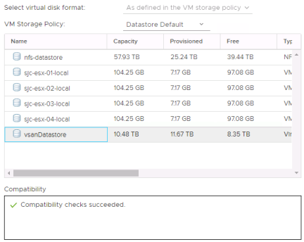
Select a storage location for the vSphere Replication Appliance
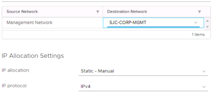
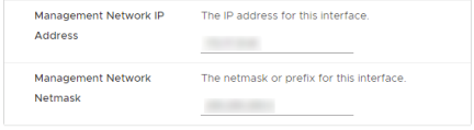
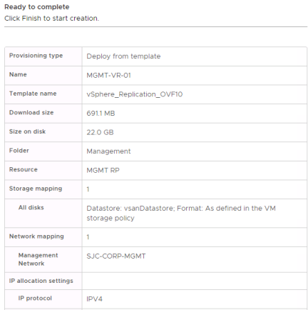
Select a network for the management interface and an IP allocation. Use a “Static – Manual” configuration for simplicity.
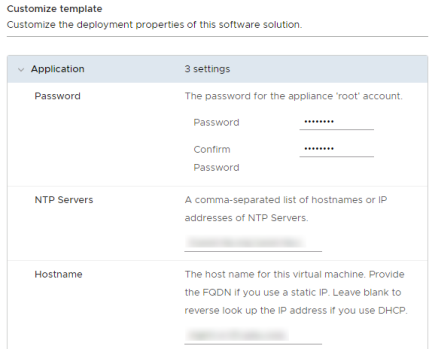
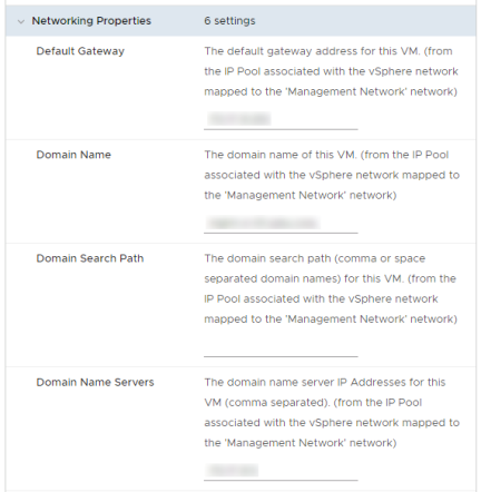
Enter the password, NTP servers, Hostname and Networking properties for the appliance and click “Next”
Click “Next” at the vCenter Extension Installation. Do not change any settings. Click “Finish”
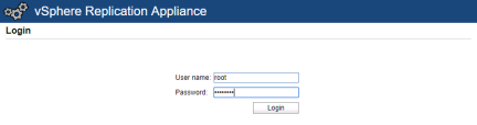
After the template has completely deployed and VMware Tools are responding, open a browser to this address: https://<mgmt IP address or DNS name>:5480
At the login screen enter the username “root” and the password entered when deploying the OVF
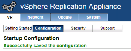
From the Getting Started screen select “Configuration”. Verify that the address of the PSC is entered in the “LookupService Address” field and then type the SSO administrator password. If desired, change the VRM Site Name.
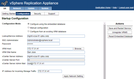
When settings are as desired, click “Save and Restart Service” to complete configuration and start services.
After configuring the vSphere Replication Appliance logout of the vSphere Web Client and then login again.
Was this information helpful
Firewall configuration
To allow communication and replication traffic between the remote site site and the VMware Cloud on AWS SDDC requires the addition of some firewall rules to the management gateway. Rules may also need to be added for the remote site firewall. Those changes are outside of the scope of this guide.
The VMware Cloud on AWS firewall provides flexibility in how strictly is configured. In a basic configuration rules are kept general to allow for a simpler setup and fewer rules. In a highly secure configuration, all aspects of the rules are explicit which results in a higher level of security and more rules. This evaluation guide will provide details about the simple configurations. For details on the highly secure configuration see the VMware Site Recovery documentation.
Simple Firewall Configuration
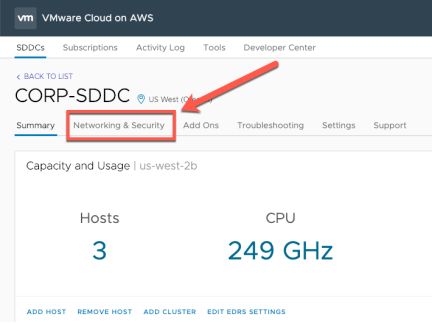
From the SDDC management page select “Networking & Security”
Select the Gateway Firewall
Click “Add New Rule”
Create the following rules (note that for a configuration between SDDCs these would need to be configured at both):
|
Name |
Source |
Destination |
Services |
|
SRM-VR Inbound to SRM |
User defined group that contains remote site SRM, VR and Admin console(s) |
VMC on AWS SRM |
VMware Site Recovery SRM |
|
SRM-VR Inbound to VR |
User defined group that contains remote site SRM, VR, ESXi hosts and Admin console(s) |
VMC on AWS VR |
VMware Site Recovery vSphere Replication |
|
SRM-VR Inbound to VC |
User defined group that contains remote site SRM, VR and Admin console(s) |
VMC on AWS vCenter |
HTTPS |
|
SRM Outbound |
System group – SRM |
Remote site group containing VC, PSC, SRM & VR |
ANY |
|
VR Outbound |
System group – VR |
Remote site group containing VC, PSC, SRM & VR |
ANY |
|
ESXi Outbound |
System group - ESXi |
Remote site group containing VR |
ANY |
Enter the rule “Name”
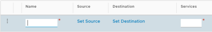
Click “Set Source”
Depending on the rule, select either system defined groups or user defined groups and select the appropriate item from the list.
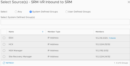
For User Defined rules if the required group doesn’t exist it can be created by clicking on “Create New Group”
Click on “Set Destination” and select the appropriate destination from the table above.
Click on the “Services” field. A dropdown will display the supported services. Choose the appropriate service from the table above.
After confirming that the rule has been entered correctly click “Publish” and then enter the next rule. Repeat until all rules have been entered.
Pair Sites
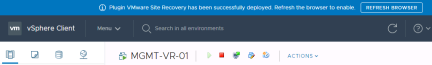
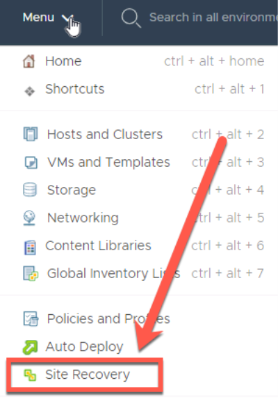
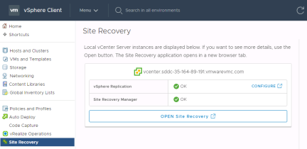
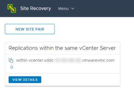
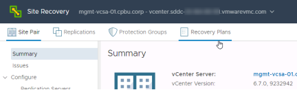
To pair VMware Site Recovery open vCenter select Menu > “Site Recovery” and click “Open Site Recovery”. This operation can be run from either the remote site or VMware Cloud on AWS vCenter.
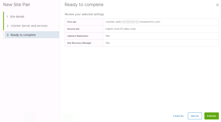
From the Site Recovery screen select “New Site Pair”
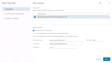
Select the vCenter for the first site, the vCenter where this workflow was started and then enter the PSC host name, user name and password for the second site. Click “Next”
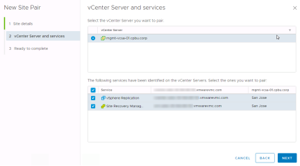
Select the vCenter you want to pair and then select both the vSphere Replication and Site Recovery Manager services. Click “Next”
Confirm the settings and click “Finish”
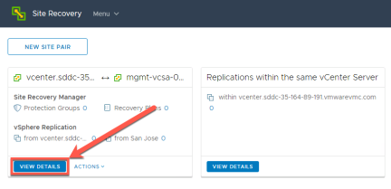
Once the pairing operation is complete the Site Recovery window now shows the site pair of Site Recovery Manager and vSphere Replication. Click “View Details to start mapping resources.
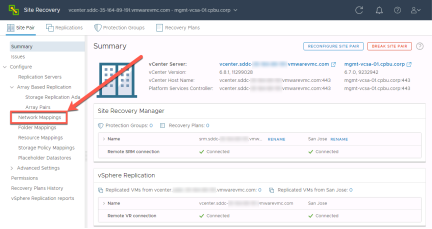
Map Resources
Inventory mappings consist of four types: Resource mappings, folder mappings, storage policy mappings and network mappings. These mappings provide default settings for recovered virtual machines. For example, a mapping can be configured between a network port group named “Production” at the remote site site and a network port group named “Production” at the VMware Cloud on AWS SDDC. As a result of this mapping, virtual machines connected to “Production” at the protected site will, by default, automatically be connected to “Production” at the recovery site.
There is no issue with having a port group at each site with the same name since each site is managed by a separate vCenter Server instance. Having port groups at each site with the same name eases VMware Site Recovery configuration. If port groups at the protected and recovery site have different names, the mappings must be created manually.
Recommendation: Provide the same name to folders and network port groups with similar functionality at the protected and recovery sites so that mappings can be prepared automatically. Use 1-1 mappings so that reverse mappings can be utilized. These practices will ease inventory-mapping configuration and minimize complexity in the environment.
Network Mapping
Select “Network Mappings” from the Site Recovery menu
Select “+New”
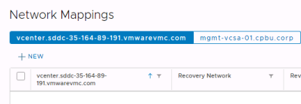
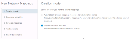
If networks are named the same at the remote site and VMware Cloud on AWS sites choose “Automatically prepare mappings” otherwise choose “Prepare mappings manually”. In this walkthrough the manual option will be selected. Click “Next”
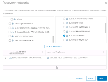
Select networks from each side, one set at a time, that need to be matched. Once they are selected click “Add Mappings” for each then click “Next”
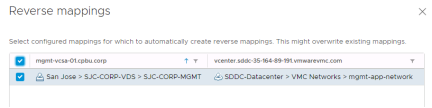
Select the networks that need to have a reverse mapping created. This is usually all networks. Click “Next”
Test Networks
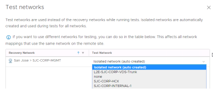
To support non-disruptive testing of recovery plans VMware Site Recovery supports connecting virtual machines to a test network when a recovery plan test is run. These networks can be one of two type:
• Isolated network (auto created)
• A regular virtual network

The isolated network is a virtual portgroup that is created on each host at the recovery site with no uplinks. The advantage of this is that no additional network configuration is required. The downside is that virtual machines on different networks and on different hosts won’t be able to communicate with each other.
Using a regular virtual network provides the advantage of simulating a production environment including the ability to conduct application testing. The challenge is that it requires work to keep the test traffic isolated. This is a challenge because currently all routed networks in VMware Cloud on AWS are routed to all others. This obviously won’t work to keep test traffic isolated from production.
In a VMware Cloud on AWS SDDC the current ways to keep test traffic isolated are:
• Stretched L2 networks to the on-premises site and route those networks at the on-premises site
• Use HCX between the on-premises site and the VMware Cloud on AWS SDDC and route traffic at the on-premises site
In this guide the auto created isolated network will be used. Click “Next”
IP Subnet Mapping
To customize IP addresses as part of failover VMware Site Recovery supports either customizing addresses on an individual virtual machine basis or, by combining network mapping with IP customization. This allows for any virtual machine that is associated with the network mapping to automatically have its IP address changed.
In the IP Customization section click “Add”
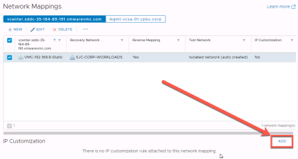
Enter the appropriate information for the source and recovery site and click “Save”
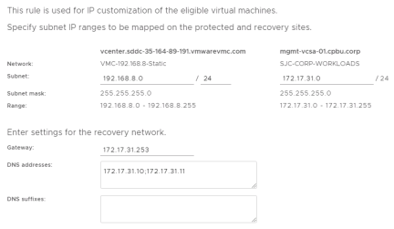
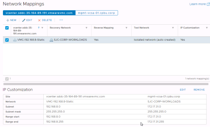
Next select the other vCenter and create the reverse IP customization rule
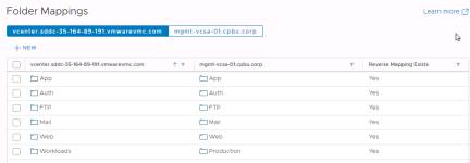
Folder Mapping
Folder mappings are much the same as network mappings without the added complexity of IP customization and test networks. To create folder mappings, select “Folder Mappings” and click “+New”.
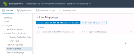
This example will show the “Automatically prepare mappings” option. Select it and click “Next”
Select the level of the hierarchy where the folder names match and click “Add Mappings” and after all mappings have been added “Next”
Select all to create reverse mappings and click “Next”
Review the settings and click “Finish”
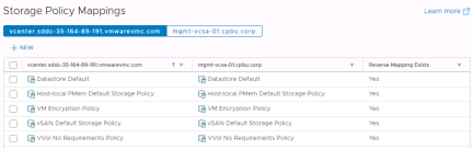
Resource Pool and Storage Policy Mapping
Resource Pool and Storage Policy mappings are handled in the same way as Folder mappings. All resources for virtual machines that will be failed over need to be mapped.

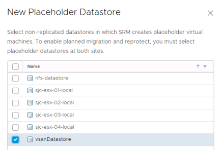
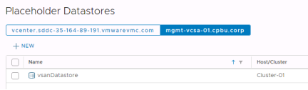
Placeholder Datastores
Placeholder datastores are used to store placeholder virtual machines. A placeholder datastore must be defined for each site. A placeholder virtual machine is a subset of virtual machine files. VMware Site Recovery uses that subset of files to register a virtual machine with vCenter Server on the recovery site.
The files of the placeholder virtual machines are very small, and do not represent full copies of the protected virtual machines. The placeholder virtual machine does not have any disks attached to it. The placeholder virtual machine reserves compute resources on the recovery site and provides the location in the vCenter Server inventory to which the protected virtual machine recovers when you run recovery.
Select “Placeholder Datastores” from the Site Recovery Menu and click “+New”
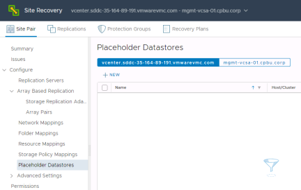
For the VMware Cloud on AWS SDDC select the Workload Datastore and click “Add”
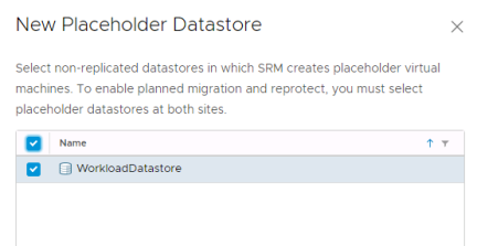
For the remote site site, choose any datastore that is accessible from all hosts and isn’t replicated.
Protect VMs
With mapping completed the next step is to start replicating and protecting virtual machines. The process of replicating virtual machines and adding them to protection groups and recovery plans is combined in VMware Site Recovery.
Replication
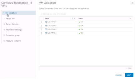
The easiest way to replicate virtual machines is to select them in the vSphere Web Client, right-click them and select “All Site Recovery actions” > “Configure Replication”
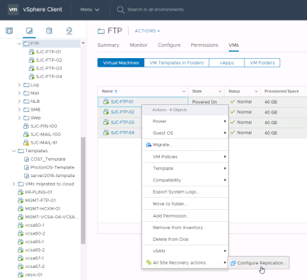
Select “Yes” to the “Open Configure replication wizard for the 4 selected virtual machines?” dialog. Confirm the correct virtual machines have been selected and click “Next”
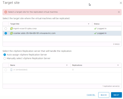
Select the target site for the replicated virtual machines. In this example we are protecting virtual machines that are running remote site so we will select our VMware Cloud on AWS SDDC. Then click “Next”
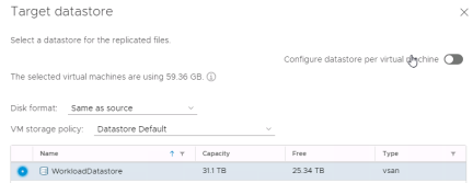
Next select the target disk format, storage policy and datastore
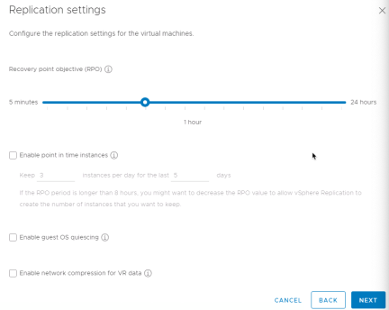
Now select replication settings. Recovery Point Objective (RPO) can be adjusted per virtual machine from 5 minutes up to 24 hours. vSphere Replication also supports guest OS quiescing for modern Windows virtual machines and some versions of Linux. If bandwidth is a concern some CPU can be traded for some bandwidth by enabling network compression. Note that point in time instances are not currently support for VMware Site Recovery. Select options and click “Next”
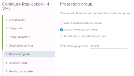
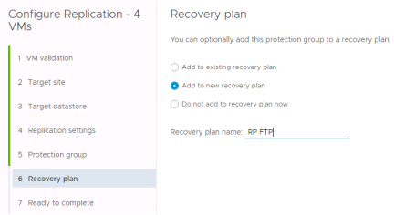
Protection Groups
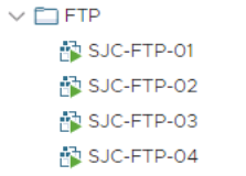
Protection groups are groups of virtual machines that are recovered together. They often are made up of all the virtual machines that make up an application. A virtual machine can only belong to a single protection group however a protection group can belong to one or more recovery plans. Workflows like failover, test and reprotect are run at the recovery plan level so this separation creates flexibility.
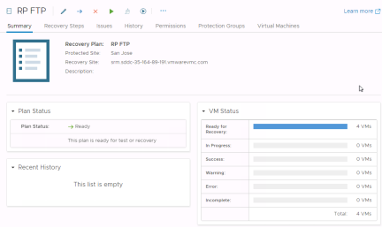
Recovery Plans
A recovery plan is like an automated run book. It controls every step of the recovery process, including the order in which VMware Site Recovery powers on and powers off virtual machines, the network addresses that recovered virtual machines use, and so on. Recovery plans are flexible and customizable.
A recovery plan includes one or more protection groups. You can include a protection group in more than one recovery plan. For example, you can create one recovery plan to handle a planned migration of services from the protected site to the recovery site for the whole organization, and another set of plans per individual departments. In this example, having these different recovery plans referencing one protection group allows you to decide how to perform recovery.
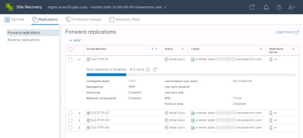
Monitoring Replications
Replication status can be monitored in the “Replications” section of the Site Recovery interface
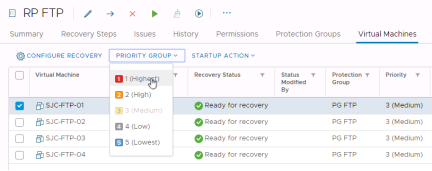
Priority Groups and Dependencies
VMware Site Recovery starts virtual machines on the recovery site according to the priority that you set. VMware Site Recovery starts priority 1 virtual machines first, then priority 2 virtual machines second, and so on. VMware Site Recovery uses VMware Tools heartbeat to discover when a virtual machine is running on the recovery site. In this way, VMware Site Recovery can ensure that all virtual machines of a given priority are running before it starts the virtual machines of the next priority. For this reason, you must install VMware Tools on protected virtual machines.
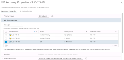
If a virtual machine depends on services that run on another virtual machine in the same protection group, you can configure a dependency between the virtual machines. By configuring a dependency, you can ensure that the virtual machines start on the recovery site in the correct order. Dependencies are only valid if the virtual machines have the same priority.
To select priority groups and create dependencies navigate to the “Recovery Plans” section and click on the recovery plan
Now select “Virtual Machines”
Select one or more virtual machines and click the “Priority Group” dropdown to adjust the priority group for them
By selecting “Configure Recovery” you will see a number of additional options.
Shutdown Actions
Shutdown actions apply to the protected virtual machines at the protected site during the run of a recovery plan. Shutdown actions are not used during the test of a recovery plan. By default, VMware Site Recovery will issue a guest OS shutdown, which requires VMware Tools and there is a time limit of five minutes. The time limit can be modified. If the guest OS shutdown fails and the time limit is reached, the virtual machine is powered off. Shutting down and powering off the protected virtual machines at the protected site when running a recovery plan is important for a few reasons:
- Quiesces the guest OS and applications before the final storage synchronization occurs
- Avoids the potential conflict of having virtual machines with duplicate network configurations (hostname, IP addresses) on the same network
Optionally, the shutdown action can be changed to simply power off virtual machines. Powering off virtual machines does not shut them down gracefully, but this option can reduce recovery times in situations where the protected site and recovery site maintain network connectivity during the run (not test) of a recovery plan. An example of this is a disaster avoidance scenario.
Recommendation: In most cases, minimizing risk and data loss are higher priorities than recovery time. Keep the default Shutdown Action setting of “Shutdown guest OS before power off” to properly quiesce the guest OS and applications, where possible, during a planned migration and disaster recovery.
Startup Actions
A startup action applies to a virtual machine that is recovered by VMware Site Recovery. Powering on a virtual machine after it is recovered is the default setting and this is typically not changed. In some cases, it might be desirable to recover a virtual machine, but leave it powered off. Startup actions are applied when a recovery plan is tested or run.
With the default setting of “Power on”, it is possible to configure the amount of time VMware Site Recovery waits for VMware Tools heartbeats before issuing an error message. VMware Tools heartbeats are used to validate a virtual machine started successfully. The default timeout value is five minutes. Changing the timeout value for this setting might be useful for virtual machines that take longer to start up. For example, if a virtual machine takes six minutes to fully boot, an error message would be produced even though the virtual machine is recovered without issue. Changing the timeout value to more than six minutes would eliminate this “false positive” error message.
Another configurable option in this section is the delay before running a post power on step, which will be covered next. A common example of a post power on step is running a script in the guest OS of a virtual machine. A delay might be needed to provide adequate time for a system service to start before running a script.
Post Power On Steps
Running a script inside of a virtual machine is supported as a post power on step.
VMware Site Recovery can also display a visual prompt as a pre or post power on step. This prompt might be used to remind an operator to place a call to an application owner, modify the configuration of a router, or verify the status of a physical machine.
Workflows
Now that virtual machines are being replicated and assigned to protection groups and recovery plans it is time to see what non-disruptive testing, failover and reprotect look like.
Test
After creating a recovery plan, it is beneficial to test the recovery plan to verify it works as expected. VMware Site Recovery features a non-disruptive testing mechanism to facilitate testing at any time. It is common for an organization to test a recovery plan multiple times after creation to resolve any issues encountered the first time the recovery plan was tested.
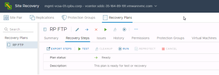
Verify the recovery plan is ready for testing or running by checking the “Plan status”. It should show “Ready”. Click the green arrow below “Recovery Plans” or click the “Test” button under the recovery steps option to begin the test process.
When testing a recovery plan, there is an option to replicate recent changes, which is enabled by default. Replicating recent changes will provide the latest data for the testing process. However, it will also lengthen the amount of time required to recover virtual machines in the recovery plan, as replication has to finish before the virtual machines are recovered.
A question often asked is whether replication continues during the test of a recovery plan. The answer is yes. VMware Site Recovery utilizes virtual machine snapshots with vSphere Replication - as part of the recovery plan test process. This approach allows powering on and modifying virtual machines recovered as part of the test while replication continues to avoid any change to RPO.
Virtual machines that are in a recovery plan that is being tested will display unique icons in the vCenter Server inventory at the recovery site.
At this point, guest operating system administrators and application owners can log into their recovered virtual machines to verify functionality, perform additional testing, and so on. VMware Site Recovery easily supports recovery plan testing periods of varying lengths - from a few minutes to several days. However, longer tests tend to consume more storage capacity at the recovery site. This is due to the nature of snapshot growth as data is written to the snapshot.
Recommendation: Closely monitor storage capacity utilization at the recovery site during recovery plan tests, if capacity is limited. Configure vCenter Server alarms to alert administrators when free space is getting low on datastores at the recovery site.
Cleanup
When testing is complete, a recovery plan must be “cleaned up”. This operation powers off virtual machines and removes snapshots associated with the test. Once the cleanup workflow is finished, the recovery plan is ready for testing or running.
Failover
Running a recovery plan differs from testing a recovery plan. Testing a recovery plan does not disrupt virtual machines at the protected site. When running a recovery plan, VMware Site Recovery will attempt to shut down virtual machines at the protected site before the recovery process begins at the recovery site. Recovery plans are run when a disaster has occurred, and failover is required or when a planned migration is desired.
Clicking the Run Recovery Plan button opens a confirmation window requiring the selection of a recovery type - either a planned migration or a disaster recovery. In both cases, VMware Site Recovery will attempt to replicate recent changes from the protected site to the recovery site. It is assumed that for a planned migration, no loss of data is the priority. A planned migration will be cancelled if errors in the workflow are encountered. For disaster recovery, the priority is recovering workloads as quickly as possible after disaster strikes. A disaster recovery workflow will continue even if errors occur.
After a recovery type is selected, the operator must also populate a confirmation checkbox as an additional safety measure. The idea behind this checkbox is to make sure the operator knows that he or she is running (not testing) a recovery plan.
The first step in running a recovery plan is the attempt to synchronize storage. Then, protected virtual machines at the protected site are shut down. This effectively quiesces the virtual machines and commits any final changes to disk as the virtual machines complete the shutdown process. Storage is synchronized again to replicate any changes made during the shutdown of the virtual machines. Replication is performed twice to minimize downtime and data loss. Once these steps have been completed, the recovery process at the recovery site is started.
If the protected site is offline due to a disaster, for example, the disaster recovery type should be selected. VMware Site Recovery will still attempt to synchronize storage as described in the previous paragraph. Since the protected site is offline, VMware Site Recovery will begin recovering virtual machines at the recovery site using the most recently replicated data.
Since running a recovery plan is a disruptive operation, VMware Site Recovery administrators commonly limit the ability to run recovery plans to just a few people in the organization. This is accomplished through VMware Site Recovery roles and permissions that are added to vCenter Server when VMware Site Recovery is installed. For example, an administrator can assign the “SRM Recovery Test Administrator” role to application owners allowing these individuals to test recovery plans for their applications, but not run recovery plans.
Recommendation: Considering the disruptive nature of running (not testing) a recovery plan, limit the permission to run a recovery plan to only a few individuals in the organization similar to the way root or domain administrator permissions are typically limited. All individuals with this permission should be fully trained on the operation of VMware Site Recovery. However, more than one person should have this permission to avoid a single point of failure.
There are several roles and permissions available. For more information on roles and permissions, see VMware Site Recovery Privileges, Roles, and Permissions in the VMware Site Recovery documentation.
Reprotect
VMware Site Recovery features the ability to not only fail over virtual machine workloads, but also fail them back to their original site. However, this assumes that the original protected site is still intact and operational. An example of this is a disaster avoidance situation: The threat could be rising floodwaters from a major storm and VMware Site Recovery is used to migrate virtual machines from the protected site to the recovery site. Fortunately, the floodwater subsides before any damage was done leaving the protected site unharmed.
A recovery plan cannot be immediately failed back from the recovery site to the original protected site. The recovery plan must first undergo a reprotect workflow. This operation involves reversing replication and setting up the recovery plan to run in the opposite direction.
Reprotecting a recovery plan can take a considerable amount of time depending on the number of protection groups and virtual machines in the recovery plan and the amount of data that must be replicated to resynchronize storage. Upon completion of the reprotect workflow, a history reports will be created, and the recovery plan can be failed back. Essentially, the original recovery site becomes the protected site and the original protected site becomes the recovery site for the virtual machines in the recovery plan. Run the recovery plan to fail back the virtual machines to their original protected site.
NOTE: Be sure to reprotect a recovery plan after it has been run (virtual machines have been failed over or failed back). Failure to do this important step will prevent future testing and running of the recovery plan until the reprotect workflow has been run.
Recommendation: Test a recovery plan as soon as possible after a reprotect workflow has run to verify the recovery plan will work properly.
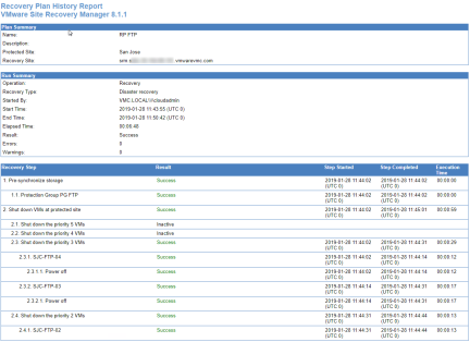
Reporting
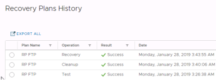
When workflows such as a recovery plan test and cleanup are performed in VMware Site Recovery, history reports are automatically generated. These reports document items such as the workflow name, execution times, successful operations, failures, and error messages. History reports are useful for a number of reasons including internal auditing, proof of disaster recovery protection for regulatory requirements, and troubleshooting. Reports can be exported to HTML, XML, CSV, or a Microsoft Excel or Word document.
Workflows
Now that virtual machines are being replicated and assigned to protection groups and recovery plans it is time to see what non-disruptive testing, failover and reprotect look like.
Test
After creating a recovery plan, it is beneficial to test the recovery plan to verify it works as expected. VMware Site Recovery features a non-disruptive testing mechanism to facilitate testing at any time. It is common for an organization to test a recovery plan multiple times after creation to resolve any issues encountered the first time the recovery plan was tested.
Verify the recovery plan is ready for testing or running by checking the “Plan status”. It should show “Ready”. Click the green arrow below “Recovery Plans” or click the “Test” button under the recovery steps option to begin the test process.
When testing a recovery plan, there is an option to replicate recent changes, which is enabled by default. Replicating recent changes will provide the latest data for the testing process. However, it will also lengthen the amount of time required to recover virtual machines in the recovery plan, as replication has to finish before the virtual machines are recovered.
A question often asked is whether replication continues during the test of a recovery plan. The answer is yes. VMware Site Recovery utilizes virtual machine snapshots with vSphere Replication - as part of the recovery plan test process. This approach allows powering on and modifying virtual machines recovered as part of the test while replication continues to avoid any change to RPO.
Virtual machines that are in a recovery plan that is being tested will display unique icons in the vCenter Server inventory at the recovery site.
At this point, guest operating system administrators and application owners can log into their recovered virtual machines to verify functionality, perform additional testing, and so on. VMware Site Recovery easily supports recovery plan testing periods of varying lengths - from a few minutes to several days. However, longer tests tend to consume more storage capacity at the recovery site. This is due to the nature of snapshot growth as data is written to the snapshot.
Recommendation: Closely monitor storage capacity utilization at the recovery site during recovery plan tests, if capacity is limited. Configure vCenter Server alarms to alert administrators when free space is getting low on datastores at the recovery site.
Cleanup
When testing is complete, a recovery plan must be “cleaned up”. This operation powers off virtual machines and removes snapshots associated with the test. Once the cleanup workflow is finished, the recovery plan is ready for testing or running.
Failover
Running a recovery plan differs from testing a recovery plan. Testing a recovery plan does not disrupt virtual machines at the protected site. When running a recovery plan, VMware Site Recovery will attempt to shut down virtual machines at the protected site before the recovery process begins at the recovery site. Recovery plans are run when a disaster has occurred, and failover is required or when a planned migration is desired.
Clicking the Run Recovery Plan button opens a confirmation window requiring the selection of a recovery type - either a planned migration or a disaster recovery. In both cases, VMware Site Recovery will attempt to replicate recent changes from the protected site to the recovery site. It is assumed that for a planned migration, no loss of data is the priority. A planned migration will be cancelled if errors in the workflow are encountered. For disaster recovery, the priority is recovering workloads as quickly as possible after disaster strikes. A disaster recovery workflow will continue even if errors occur.
After a recovery type is selected, the operator must also populate a confirmation checkbox as an additional safety measure. The idea behind this checkbox is to make sure the operator knows that he or she is running (not testing) a recovery plan.
The first step in running a recovery plan is the attempt to synchronize storage. Then, protected virtual machines at the protected site are shut down. This effectively quiesces the virtual machines and commits any final changes to disk as the virtual machines complete the shutdown process. Storage is synchronized again to replicate any changes made during the shutdown of the virtual machines. Replication is performed twice to minimize downtime and data loss. Once these steps have been completed, the recovery process at the recovery site is started.
If the protected site is offline due to a disaster, for example, the disaster recovery type should be selected. VMware Site Recovery will still attempt to synchronize storage as described in the previous paragraph. Since the protected site is offline, VMware Site Recovery will begin recovering virtual machines at the recovery site using the most recently replicated data.
Since running a recovery plan is a disruptive operation, VMware Site Recovery administrators commonly limit the ability to run recovery plans to just a few people in the organization. This is accomplished through VMware Site Recovery roles and permissions that are added to vCenter Server when VMware Site Recovery is installed. For example, an administrator can assign the “SRM Recovery Test Administrator” role to application owners allowing these individuals to test recovery plans for their applications, but not run recovery plans.
Recommendation: Considering the disruptive nature of running (not testing) a recovery plan, limit the permission to run a recovery plan to only a few individuals in the organization similar to the way root or domain administrator permissions are typically limited. All individuals with this permission should be fully trained on the operation of VMware Site Recovery. However, more than one person should have this permission to avoid a single point of failure.
There are several roles and permissions available. For more information on roles and permissions, see VMware Site Recovery Privileges, Roles, and Permissions in the VMware Site Recovery documentation.
Reprotect
VMware Site Recovery features the ability to not only fail over virtual machine workloads, but also fail them back to their original site. However, this assumes that the original protected site is still intact and operational. An example of this is a disaster avoidance situation: The threat could be rising floodwaters from a major storm and VMware Site Recovery is used to migrate virtual machines from the protected site to the recovery site. Fortunately, the floodwater subsides before any damage was done leaving the protected site unharmed.
A recovery plan cannot be immediately failed back from the recovery site to the original protected site. The recovery plan must first undergo a reprotect workflow. This operation involves reversing replication and setting up the recovery plan to run in the opposite direction.
Reprotecting a recovery plan can take a considerable amount of time depending on the number of protection groups and virtual machines in the recovery plan and the amount of data that must be replicated to resynchronize storage. Upon completion of the reprotect workflow, a history reports will be created, and the recovery plan can be failed back. Essentially, the original recovery site becomes the protected site and the original protected site becomes the recovery site for the virtual machines in the recovery plan. Run the recovery plan to fail back the virtual machines to their original protected site.
NOTE: Be sure to reprotect a recovery plan after it has been run (virtual machines have been failed over or failed back). Failure to do this important step will prevent future testing and running of the recovery plan until the reprotect workflow has been run.
Recommendation: Test a recovery plan as soon as possible after a reprotect workflow has run to verify the recovery plan will work properly.
Reporting
When workflows such as a recovery plan test and cleanup are performed in VMware Site Recovery, history reports are automatically generated. These reports document items such as the workflow name, execution times, successful operations, failures, and error messages. History reports are useful for a number of reasons including internal auditing, proof of disaster recovery protection for regulatory requirements, and troubleshooting. Reports can be exported to HTML, XML, CSV, or a Microsoft Excel or Word document.
- Yes
- No