
Using VMware Cloud Disaster Recovery and HCX Stretched Networks
Executive Overview
Some of the most important considerations around architecting for a comprehensive disaster recovery (DR) solution are the network considerations. In this document, we will walk through some of the most common DR testing or outage scenarios and describe how VMware technologies, such as VMware Cloud Disaster Recovery™ and VMware HCX®, can assist in providing a comprehensive framework for architecting and delivering robust disaster recovery to cloud.
Many organizations find it necessary to keep networking changes to a minimum when building a DR solution. This frequently means maintaining IP addresses for systems that are being recovered during failover or testing exercises. This white paper will review the scenarios that could warrant a disaster recovery failover or test, and explore options and considerations for maintaining current IP addresses between production and failover environments. While this white paper is primarily focused on leveraging VMware HCX for network extensions, the conceptual consideration of each situation is the same with or without VMware HCX.
VMware Cloud Disaster Recovery and VMware HCX make the complex strategy around disaster recovery far simpler, providing a modern DR solution using public cloud resources in an operationally consistent fashion. Our goal is to make disaster recovery objectives achievable, ensure recovery time and recovery point objectives (RTO/RPO) are met each time in a measurable fashion, and reduce costs and complexities of DR.
This document is intended to highlight different disaster recovery and test scenarios using VMware Cloud Disaster Recovery and VMware HCX, providing high-level guidance for the implementation considerations for each scenario. This document is not designed to provide a step-by-step usage guide for the solutions mentioned (VMware HCX, VMware Cloud Disaster Recovery, and VMware Cloud™ on AWS). Detailed documentation and usage guides for these solutions are available at:
- docs.vmware.com/en/VMware-Cloud-on-AWS
- docs.vmware.com/en/VMware-Cloud-Disaster-Recovery
- docs.vmware.com/en/VMware-HCX
For the purposes of this white paper, the VMware Cloud on AWS M14 release with the VMware HCX add-on as well VMware Cloud Disaster Recovery version 7.21.4 have been used.
Solution Overview
VMware Cloud Disaster Recovery
VMware Cloud Disaster Recovery protects your virtual machines (VMs), on premises or on VMware Cloud on AWS, by replicating them to the cloud and recovering them to a VMware Cloud on AWS software-defined data center (SDDC).
VMware Cloud Disaster Recovery provides the following main features and benefits:
- Comprehensive SaaS simplicity across DR automation, on-demand failover recovery and site preparedness, the SCFS for cloud backup, and failback
- Live mount snapshots from the cloud provides the ability for hosts in VMware Cloud on AWS to boot VMs directly from copies stored securely in cloud backup (SCFS); the cloud backup site acts as an NFS datastore for the recovery SDDC
- Cost optimized: Pay-per-use DR site in public cloud, restarting VMs from low-cost cloud backup storage
- Disaster and cybercrime recovery based on backups
- Continuous DR compliance checks
- Automated compliance reporting
- End-to-end security
VMware Cloud Disaster Recovery manages all aspects of AWS and VMware Cloud, based on your parameters, with complete runbook automation. For maximum simplicity, the recovery site is VMware Cloud on AWS. As a result, there is a consistent operating environment that seamlessly spans primary and recovery sites. VMware vCenter® remains the operating console, VMs still have VMware characteristics without conversion, hosts are still hosts, and distributed resource schedule (DRS) and high availability (HA) continue as usual.
VMware HCX
VMware HCX, an application mobility platform, simplifies application migration, workload rebalancing, and business continuity across data centers and clouds. VMware HCX enables high-performance, large-scale app mobility across VMware vSphere® and non-vSphere cloud and on-premises environments to accelerate data center modernization and cloud transformation. VMware HCX automates the creation of an optimized network interconnect and extension, and facilitates interoperability across KVM, Hyper-V and older vSphere versions under extended support (within Technical Guidance) up through vSphere versions. This delivers live and bulk migration capabilities without redesigning the application or re-architecting networks.
VMware HCX abstracts on-premises and cloud resources based on vSphere and presents them to applications as one continuous resource. An encrypted, high-throughput, WAN-optimized, load-balanced, traffic-engineered hybrid interconnect automates the creation of a network extension. This allows support for hybrid services, such as application migration, workload rebalancing, and optimized disaster recovery. With a VMware HCX hybrid interconnect in place, applications can reside anywhere, independent of the hardware and software underneath.
Mobility Optimized Networking
When extending networks to a remote VMware NSX-T™ Data Center, you can enable the VMware HCX Mobility Optimized Networking service to route the network traffic based on the locality of the source and destination virtual machines.
This service ensures traffic from the local and remote data centers uses an optimal path to reach its destination, while all flows remain symmetric.
In the absence of Mobility Optimized Networking, all traffic from workloads on an extended network at the destination site is routed through the source environment router.
Network Extension with VMware HCX Mobility Optimized Networking provides the following functionality:
- Enable or disable Mobility Optimized Networking at the time of stretching a network
- Enable or disable Mobility Optimized Networking for already extended networks
- Enable or disable Mobility Optimized Networking on an individual VM basis for VMs residing on extended networks in the SDDC
- Display which VMs are using Mobility Optimized Networking
When using VMware HCX to migrate a VM, preserve existing network connections by providing enabling Mobility Optimized Networking on that VM after migration.
Note: The use of HCX Mobility Optimized Networking is not currently supported generally for disaster recovery use cases, nor specifically with VMware Cloud Disaster Recovery. Networks configured for use with HCX Mobility Optimized Networks are supported as virtual machine networks in VMware Cloud on AWS, but not for use as recovery networks when used with VMware Cloud Disaster Recovery.
Solution Testing Architecture
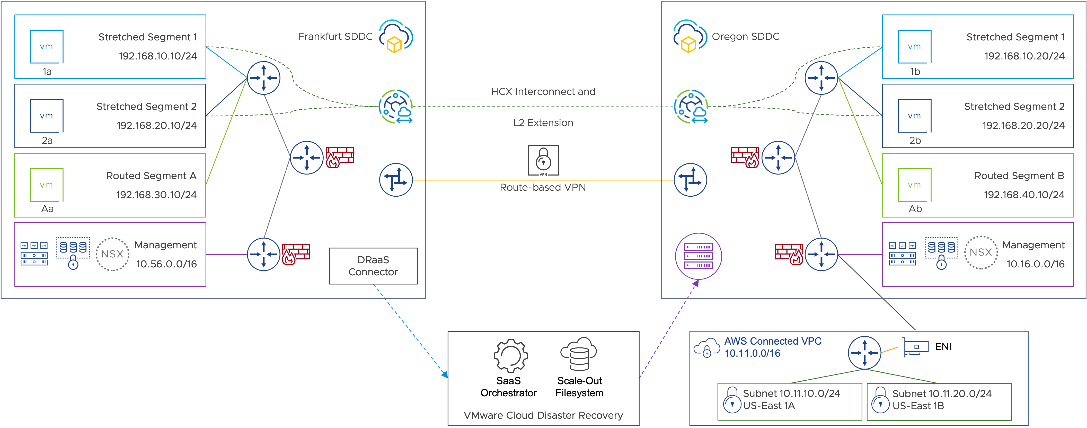
Figure 1: Testing environment overview.
Overview
For the purposes of this white paper, a VMware Cloud on AWS SDDC is deployed in the Europe (Frankfurt) region and is configured as the source data center where primary workloads are running. The Frankfurt SDDC is leveraging VMware Cloud Disaster Recovery for protection, and a second SDDC located in the U.S. West (Oregon) region is used as the recovery site. Both SDDCs are up and running with the Oregon SDDC running as a minimal, pilot light cluster with only two running VMware ESXi™ hosts. This SDDC will scale up with more on-demand hosts as needed to provide adequate capacity for disaster recovery. Distinct, routed, network segments for management and compute (A and B) have been deployed at each site, and a route-based VPN has been established between the two sites, providing routing and connectivity across the SDDCs.
VMware HCX (included as an add-on for VMware Cloud on AWS) is deployed at both sides, and a service mesh between the two SDDCs provides extended layer-2 (L2) segments (Extended Segment 1 and 2) across the two sites. These VMware HCX L2 extensions allow virtual machines to sit on the same layer-2 broadcast domain in either site. This approach also eliminates the need to manually create segments and enter IP addressing information during an outage event - effectively minimizing the possibility of configuration errors. This means during steady-state operations, the same IP segment is available in both the source and destination sites, with the default gateway of the subnet remaining in Frankfurt:
- VM1a and VM1b are deployed on extended segment 1 with IP addresses of 192.168.10.10 and 192.168.10.20 respectively, with the default gateway of 192.168.10.1 being in Frankfurt.
- VM2a and VM2b are deployed on extended segment 2 with IP addresses of 192.168.20.10 and 192.168.20.20 respectively, with the default gateway of 192.168.20.1 being in Frankfurt.
- VMAa is deployed in the local routed segment 192.168.30.0/24 in Frankfurt with IP address of 192.168.30.10 with a local .1 default gateway
- VMBa is deployed in the local routed segment 192.168.40.0/24 at Oregon with IP address of 192.168.30.10 with a local .1 default gateway.
- These segments can communicate to other segments either across the route-based layer-3 VPN tunnel or using the local gateways at Frankfurt, depending on destination.
A VMware Cloud Disaster Recovery connector appliance is deployed in the Frankfurt SDDC, replicating VM1a, VM2a and VMAa into the VMware Cloud Disaster Recovery instance in Oregon. Each VM is configured with a dedicated protection group and DR plan in the VMware Cloud Disaster Recovery orchestrator that will recover these virtual machines into Oregon with custom configurations.
Both SDDCs also are connected to an AWS Virtual Private Cloud (VPC) with the standard Elastic Network Interface (ENI) that is deployed as part of each VMware Cloud on AWS SDDC in the respective regions.

Figure 2: Virtual machine network flow with VMware HCX Mobility Optimized Networking disabled.
As shown in Figure 2:
- VM1b (192.168.10.20) sends an ICMP Echo request (PING test) to VM2b (192.168.20.20).
- Packet traverses the L2 extension via VMware HCX for Stretched Segment 1 back to the on-premises default gateway (192.168.10.1).
- Packet is routed via the on-premises default gateway to Stretched Segment 2 (192.168.20.0/24).
- Packet traverses the L2 extension via VMware HCX for Stretched Segment 2 to the cloud SDDC.
- Packet arrives at VM2b (192.168.20.20).
Note: Networks configured for use with HCX Mobility Optimized Networks are supported as virtual machine networks in VMware Cloud on AWS, but not for use as recovery networks when used with VMware Cloud Disaster Recovery.
Outage Scenarios
There are several outage scenarios that might result in sufficient interruption to business to require an organization to fail critical services or applications over to an alternative environment. Whether natural or human-caused, it is important to identify what types of outage scenarios your organization might be at risk for, as well as those your organization desires to address. In this paper, we are examining situations that might cause a connectivity outage of some kind for either an entire site or one impacting specific workloads. While we will be specifically addressing infrastructure outages related to networking, some of the outage scenarios may be applicable to an outage of any kind, such as an outage of storage, hosts, individual server components, and the like.
Outage scenario 1: Outage of source site

Figure 3: Outage of source site.
Scenario Overview
One of the most common outage scenarios our customers wish to address is the complete outage of an entire site. This could be due to the loss of power to a building or region, a weather-related event that damages or destroys property or infrastructure, or something more nefarious, such as an infection of malware or ransomware. Whatever the cause, this scenario assumes the complete loss of services from the primary service site.
Before you begin
The following steps were used to simulate the actual outage and recovery of services as previously described. In an actual outage of your production site, your steps may vary.
Firewall rules at the source and destination need to be consistent to ensure all failover workloads can operate the same as production in the DR environment. Be sure to configure appropriate firewall rules, network segments, NAT rules (etc) as much as possible in advance to minimize the necessary effort during an actual outage. In the following steps, we update the firewall rules at the destination SDDC. This may or may not be needed in customer environments if the rules already exist.
Execution summary
Failover
- Networking and communications are disabled and unavailable in the production site.
- Change name resolution for one of the VMware HCX managers to disable communications between VMware HCX managers.
- Disconnect the VMnic for the VMware HCX Interconnect (IX) and Network Extension (L2e) appliances to simulate outage of the service mesh.
- Network extensions are forcibly unextended in the SDDC (and on premises, if possible).
- Networks in the destination SDDC are set as routable segments.
- Disaster recovery plans are executed to fail into the destination SDDC.
Failback
- VPN/network connectivity is reestablished.
- Networks are re-extended.
- Failback plans are executed.
Test results
Workloads are able to recover into the destination SDDC and come online with original IP addresses.
Steps to replicate test
- Disconnect or disable the VPN.

Figure 4:VPN is disabled.
- Force unextend of the network on the local/source side. Forcing the network to unextend is necessary as the VMware HCX managers will not be able to communicate. In a true outage situation, it may not be possible to execute this step.

Figure 5:Force unextend networks on premises.
- Force unextend the network in the cloud/recovery SDDC. Forcing the network to unextend is necessary as the VMware HCX managers will not be able to communicate. Check the box to allow the VMware HCX manager in the destination SDDC to connect the cloud network to the cloud edge gateway for routing capabilities.

Figure 6:Force unextend networks in the SDDC.

Figure 7:Connect the segment to the edge gateway router in the SDDC during the unextend operation.

Figure 8:Unextend in progress.
- Update the destination network in the cloud to routed (if not already set to routed by VMware HCX). Note: This is a manual task, performed in the SDDC Networking and Security page. It is possible to automate this by using the NSX-T API for VMware Cloud on AWS.

Figure 9:Changing the network type from Disconnected to Routed.

Figure 10:Changing the network type from Disconnected to Routed.

Figure 11: Cloud segments updated to Routed.
- Update firewall rules to allow inbound/outbound access to and from the newly routed network segments.

Figure 12: Update SDDC compute gateway firewall to allow communications to new routed segments.

Figure 13: Updated rules allow inbound and outbound traffic to new, routed segments.

Figure 14: Selecting the failover network.
- Failover DR plans.
![]()
Figure 15: Failover DR plan.
- Confirm IP address of the failover workloads and test connectivity.

Figure 16: Recovered workload confirming IP address.

Figure 17: Recovered workload confirming connectivity to other networks in the SDDC.

Figure 18: Recovered workload confirming internet connectivity.
Outage scenario 2: Outage of internet/WAN

Figure 19: Partial outage; outage of internet/WAN.
Scenario overview
In this case, WAN/internet connectivity has failed, cutting off communications from the production data center on premises to the VMware Cloud on AWS SDDC, housing its own production workloads. Even though the nature of this scenario results from a fundamentally different type of outage scenario, functionally speaking, this is the same as outage scenario 1. For those workloads deemed critical, if a disaster is declared, all impacted/flagged workloads will have to be recovered into the VMware Cloud on AWS SDDC.
Before you begin
The following step were used to simulate the actual outage and recovery of services as previously described. In an actual outage of your production site, your steps may vary.
Firewall rules at the source and destination need to be consistent to ensure all failover workloads can operate the same as production in the DR environment. Be sure to configure appropriate firewall rules, network segments, NAT rules (etc) as much as possible in advance to minimize the necessary effort during an actual outage. In the following steps, we update the firewall rules at the destination SDDC. This may or may not be needed in customer environments if the rules already exist.
Execution summary
Failover
- Networking and communications are disabled and unavailable in the production site.
- Change name resolution for one of the VMware HCX managers to disable communications between managers.
- Disconnect the VMnic for IX and L2e to simulate outage of a HCX Service Mesh
- (see https://docs.vmware.com/en/VMware-HCX/4.5/hcx-user-guide/GUID-5D2F1312-EB62-4B25-AF88-9ADE129EDB57.html for a description of the HCX Service Mesh).
- Network extensions are forcibly unextended.
- Networks in the destination SDDC are set as routable segments.
- Disaster recovery plans are executed to fail into the destination SDDC.
Failback
- VPN/network connectivity is reestablished.
- Networks are re-extended.
- Failback plans are executed.
Steps to replicate test
Follow the same steps for Outage scenario 1: Outage of source site, page 7.
Test results
Workloads are able to recover into the destination SDDC and come online with original IP addresses.
Outage scenario 3: Outage of specific workloads or application

Figure 20: Partial outage; specific workloads impacted.
Scenario overview
There are a variety of situations that might occur causing individual applications or workloads to fail in the primary data center. In this scenario, we are demonstrating a particular workload/application outage where a set of virtual machines that make up that application need to be failed over to the disaster recovery location, maintaining their networking information consistent.
Before you begin
The following steps were used to simulate the actual outage and recovery of services as previously described. In an actual outage of your production site, your steps may vary. Be sure to configure appropriate firewall rules, network segments, NAT rules (etc) as much as possible in advance to minimize the necessary effort during an actual outage.
Execution summary
Failover
- Disaster recovery plans are executed to fail into the destination SDDC.
- No changes to VMware HCX or routing should be necessary, assuming the workload(s) fail into a stretched network.
- Ancillary application components, such as load balancers, may need to be updated.
Failback
- Disaster recovery plans are executed to fail into the destination SDDC.
- No changes to VMware HCX or routing should be necessary, assuming the workload(s) fail into a stretched network.
Test results
Virtual machines will fail into the corresponding extended network in the SDDC and still be able to communicate with other virtual machines in the SDDC or source data center as they were able to prior to the failover.
Steps to replicate test
- Validate DR plan to ensure failover and test mapping land the virtual machines in the appropriate production network that is currently extended and remove any IP address change/update rules. Note: You can still use the IP address rules to update DNS or default gateway addresses if custom values are needed during failover or you want to use a virtual machine/appliance router in the recovered segment.

Figure 21: DR runbooks have the same destination virtual network mapped for test and failover.

Figure 22: DR plan does not change the IP address of the VMs.
- Execute the DR test.
![]()
Figure 23: Test DR plan.
- After the recovery, the recovered VM2a has retained its production IP address and is able to communicate to VM2b on the local segment.

Figure 24: The virtual machine has retained its production IP address post recovery.

Figure 25: Recovered VM can communicate with the other VM on the same segment.
- Confirm that the recovered VM has retained its production IP address.

Figure 26: Recovered workload confirming IP address.
- The recovered VM is able to communicate with other routed subnets in the SDDC.

Figure 27: Recovered workload confirming connectivity to other VMware HCX extended segments.
Outage scenario 4: Outage of specific on-premises segment(s)

Figure 28: Partial outage; on-premises networking impacted for some networks.
Scenario overview
In this case, one or more on-premises segments are impacted due to a network outage. This scenario assumes a complete outage for the entire network segment(s). In any segment for which a disaster is declared, any workloads protected and replicated to the disaster recovery site failover to maintain full functionality.
Before you begin
The following steps were used to simulate the actual outage and recovery of services as previously described. In an actual outage of your production site, your steps may vary.
Firewall rules at the source and destination need to be consistent to ensure all failover workloads can operate the same as production in the DR environment. Be sure to configure appropriate firewall rules, network segments, NAT rules (etc) as much as possible in advance to minimize the necessary effort during an actual outage. In the following steps, we update the firewall rules at the destination SDDC. This may or may not be needed in customer environments if the rules already exist.
Execution summary
Failover
- Internal routing and route distribution is updated for any networks failed over and advertised from the recovery SDDC.
- Network extensions for impacted segments are forcibly unextended.
- Networks in the destination SDDC are set as routable segments.
- Disaster recovery plans are executed to fail into the destination SDDC.
Failback
- Networks are re-extended.
- Failback plans are executed.
Test results
Workloads from the impacted network segment(s) are failed into the recovery site, maintaining existing IP address configuration, and establishing connectivity with remaining workloads and resources.
Steps to replicate test
- Take action on premises to prevent routing conflict/BGP advertising conflicts.
- Force unextend the network on the local/source side (if possible). Forcing the network to unextend is necessary, as the VMware HCX managers will not be able to communicate.

Figure 29: Stretched networks in the SDDC.
Figure 30: Force unextend networks on premises.
- Ensure the local segment is disconnected/isolated to prevent routing conflicts over the VPN.

Figure 31: On-premises network disconnected/isolated.
- Ensure internal routing and route distribution are updated to prevent the failed network subnet from being advertised to the recovery SDDC.
- Force unextend the network in the cloud/recovery SDDC. Forcing the network to unextend is necessary, as the VMware HCX managers will not be able to communicate. Check the box to allow the VMware HCX manager in the destination SDDC to connect the cloud network to the cloud edge gateway for routing capabilities.
Figure 32: Force unextend networks in the SDDC.

Figure 33: Connect the segment to the edge gateway router in the SDDC during the unextend operation.
Figure 34: Unextend in progress.

Figure 35: SDDC segment shown as routed once the unextend is complete.
- Update the destination network in the cloud to routed (if not already set to routed by VMware HCX). Note: This is a manual task, performed in the SDDC Networking and Security page. It is possible to automate this by using the NSX-T API for VMware Cloud on AWS.
Figure 36: Changing the network type from Disconnected to Routed.
Figure 37: Changing the network type from Disconnected to Routed.
Figure 38: Cloud segments updated to Routed.
- If using a policy-based VPN, be sure to update the VPN configuration to properly reflect use of the segment subnet in VMware Cloud on AWS.
- Update firewall rules to allow inbound/outbound access to and from the newly routed network segments.
Figure 39: Update SDDC compute gateway firewall to allow communications to new routed segments.
Figure 40: Updated rules allow inbound and outbound traffic to new, routed segments.

Figure 41: Selecting the failover network.
- Failover DR plans.
![]()
Figure 42: Failover DR plan.
- Confirm IP address of the failover workloads and test connectivity.
Figure 43: Recovered workload confirming IP address.
Figure 44: Recovered workload confirming connectivity to other networks in the SDDC.

Figure 45: Recovered workload confirming internet connectivity.
Failback
- Extend the networks again from the source SDDC.
- Ensure destination networks are now disconnected as part of the extend.
- Update internal routing if needed to advertise routes from the original site.
- Failback DR plans.
Outage scenario 5: Outage of all VMware HCX infrastructure

Figure 46: Partial outage; VMware HCX outage.
Scenario overview
In this outage scenario, we address the outage of the VMware HCX infrastructure itself - including the appliances participating in the Service Mesh. If the VMware HCX infrastructure, appliances or service mesh fail, any network segments stretched from the protected site to the recovery site will fail in the recovery site. Assuming production workloads are running both on premises and in the recovery SDDC, any workloads protected and replicated to the disaster recovery site failover to maintain full functionality and connectivity to the remaining production workloads in the recovery site.
Functionally, then, this scenario is fundamentally the same as scenario 4, except multiple network segments may be impacted rather than a single segment.
Before you begin
The following steps were used to simulate the actual outage and recovery of services as previously described. In an actual outage of your production site, your steps may vary.
Firewall rules at the source and destination need to be consistent to ensure all failover workloads can operate the same as production in the DR environment. Be sure to configure appropriate firewall rules, network segments, NAT rules (etc) as much as possible in advance to minimize the necessary effort during an actual outage. In the following steps, we update the firewall rules at the destination SDDC. This may or may not be needed in customer environments if the rules already exist.
Execution summary
Failover
- Networking and communications are disabled and unavailable in the production site.
- Change name resolution for one of the VMware HCX managers to disable communications between managers.
- Disconnect the VMnic for IX and L2e to simulate outage of SM.
- Network extensions are forcibly unextended in the SDDC (and on premises, if possible).
- Networks in the destination SDDC are set as routable segments.
- Disaster recovery plans are executed to fail into the destination SDDC.
Failback
- VPN/network connectivity is reestablished.
- Networks are re-extended.
- Failback plans are executed.
Test results
Workloads from the impacted network segment(s) are failed into the recovery site, maintaining existing IP address configuration, and establishing connectivity with remaining workloads and resources.
Steps to replicate test
- Shut down/suspend VMware HCX at the source SDDC or disconnect the appliance NICs.

Figure 47: Confirming VMware HCX service mesh down.
- Take action on premises to prevent routing conflict/BGP advertising conflicts.
- Force unextend the network on the local/source side (if possible). Forcing the network to unextend is necessary as the VMware HCX managers will not be able to communicate.
Figure 48: Stretched networks in the SDDC.
Figure 49: Force unextend networks on premises.
- Ensure the local segment is disconnected/isolated to prevent routing conflicts over the VPN.
Figure 50: On-premises network disconnected/isolated.
- Ensure internal routing and route distribution are updated to prevent the failed network subnet from being advertised to the recovery SDDC.
- Force unextend the network in the cloud/recovery SDDC. Forcing the network to unextend is necessary as the VMware HCX managers will not be able to communicate. Allow the VMware HCX manager in the destination SDDC to connect the cloud network to the cloud edge gateway for routing capabilities.
Figure 51: Force unextend networks in the SDDC.
Figure 52: Connect the segment to the edge gateway router in the SDDC during the unextend operation.
Figure 53: Unextend in progress.
Figure 54: SDDC segment shown as Routed once the unextend is complete.
- Update the destination network in the cloud to routed (if not already set to routed by VMware HCX). Note: This is a manual task, performed in the SDDC Networking and Security page. It is possible to automate this by using the NSX-T API for VMware Cloud on AWS.
Figure 55: Changing the network type from Disconnected to Routed.
Figure 56: Changing the network type from Disconnected to Routed.
Figure 57: Cloud segments updated to Routed.
- If using a policy-based VPN, be sure to update the VPN configuration to properly reflect use of the segment subnet in VMware Cloud on AWS.
- Update firewall rules to allow inbound/outbound access to and from the newly routed network segments.
Figure 58: Update SDDC compute gateway firewall to allow communications to new routed segments.
Figure 59: Updated rules allow inbound and outbound traffic to new, routed segments.

Figure 60: Selecting the failover network.
- Failover DR plans.
![]()
Figure 61: Failover DR plan.
- Confirm IP address of the failover workloads and test connectivity.
Figure 62: Recovered workload confirming IP address.
Figure 63: Recovered workload confirming connectivity to other networks in the SDDC.
Figure 64: Recovered workload confirming internet connectivity.
Failback
- Reconnect VMware HCX appliances or recover the service mesh.
- Extend the network(s).
- Failback the virtual machines.
DR Test Scenarios
Testing your recovery plan is in some ways equally complicated and risky than an actual DR event. Continuity of service while simulating and testing the outage of those services poses a real threat of actual outage for one or more applications. VMware Cloud Disaster Recovery provides the capability to bring a copy of applications online leveraging a different networking configuration for the test than that which will be used for an actual failover. This capability, while providing enormous flexibility, also introduces complexity that must be fully examined to ensure desired outcomes are achieved. The test scenarios detailed in the following section represent the three most likely desired outcomes for testing workload failover as a result of one of the outage scenarios.
Test scenario 1: Performing a test recovery with changed workload IP address
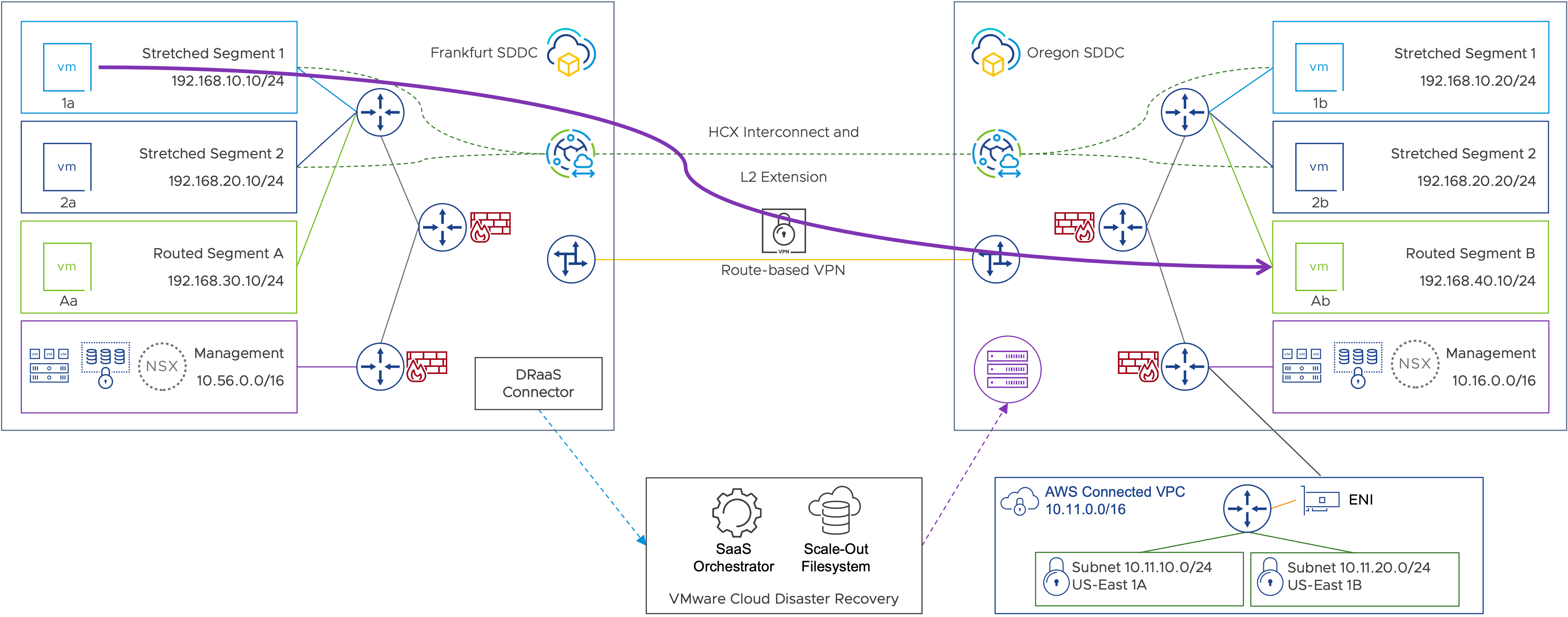
Figure 65: Performing a test recovery with changed workload IP address.
Scenario overview
In this DR test, we will be recovering the in-scope virtual machines in the recovery SDDC. During a DR test, a copy of the virtual machine is recovered into the recovery SDDC from a recovery point of choice without impacting the production VM. In this test, the recovered virtual machines will be landed in a dedicated routed segment (Segment B) in the SDDC, and the VMware Cloud Disaster Recovery DR plan will automatically update the IP addresses to match the recovery subnet. Connectivity between the production site and the recovery SDDC will also remain in place, and routing is possible between recovered virtual machines and production. Firewall rules can be used to restrict connectivity.
For our example, we will be recovering a snapshot for VM1a into Routed Segment B, and the IP addresses for the recovered virtual machine will be changed to the 192.168.40.0/24 subnet.
Before you begin
The following steps were used to simulate the testing of failover and recovery of services as previously described. Be sure to configure appropriate firewall rules, network segments, NAT rules (etc) as much as possible in advance to minimize the necessary effort during an actual outage.
In an actual test of your VMware Cloud DR Plan your steps may vary.
- Local pings will work.
- Ping across to the source site will work as well.
- Distributed firewall or compute gateway firewall rules can be used to further restrict VM traffic.
Execution summary
- Test into 192.168.40.x.
- Modify the test plan to land on the .40 segment.
- Change IP mapping for the test to provide the .40 address to the failed-over VM.
- Clean up the DR test.
If the SDDC is part of an SDDC Group, do perform a forced unextend. This will ensure stretched networks are properly connected as routed compute segments to the NSX-T Tier-1 router and advertised to the VMware-managed Transit Gateway.
Test results
- The recovered VM now has a new IP in the assigned recovery subnet.
- Ping works to local segments.
- Ping works to other, local, routed segments and connected VPC (where firewall rules allow).
- Ping to on-premises/source gateway and virtual machines also work.
Steps to replicate the test
- Update DR plan and use test mapping under virtual network to use a separate mapping for a DR test compared to a failover.

Figure 66: DR plan with different failover and test virtual networks mapping.
- Select the appropriate network in the recovery SDDC that will be used for the DR test in the plan.

Figure 67: DR plan showing DR test virtual networks mapping.
- Update IP address rules and create rule to re-IP recovered virtual machine.

Figure 68: Change IP address rule.
- Save re-IP rule under IP address for test mapping.

Figure 69: DR plan updating VM IP address during DR test.
- Save plan and execute test plan.
![]()
Figure 70: Test DR plan.
- Once VM1a is recovered in the DR test, we can see that it now has a new IP address in the Routed Segment B network.

Figure 71: Recovered workload confirming assignment of new IP address.
- The recovered VM1a is now able to reach the local gateway in the recovery SDDC.

Figure 72: Recovered workload confirming IP connectivity to the same subnet.
- The recovered VM is also able to reach across to the production workloads in the source environment.

Figure 73: Recovered workload confirming IP connectivity to other routed subnets.
- It is also able to reach other subnets within the recovery SDDC, as expected.

Figure 74: Recovered workload confirming connectivity to other subnets.
Test scenario 2: Performing a test recovery into a routed network with the same IP address

Figure 75: Performing a test recovery into a routed network with the same IP address.
Scenario overview
In this DR test, we will be recovering the in-scope virtual machines in the recovery SDDC. During a DR test, a copy of the virtual machine is recovered into the target SDDC from a snapshot without impacting the production VM. In this test, the virtual machines will be recovered in an extended segment (Segment 1) in the SDDC and the DR plan will not change the recovered VM’s IP address. Connectivity between source and recovery sites will be disabled, and networks will be unextended to ensure the DR test environment is isolated and there are no routing conflicts with production or duplicate IP addresses.
For our example, we will be recovering a recovery point for VM1a into Stretched Segment 1. The virtual machine will retain its production IP address; however, the DR site is disconnected from production and Segment 1 network is now locally routed in the recovery site.
Before you begin
The following steps were used to simulate the testing of failover and recovery of services as previously described. Be sure to configure appropriate firewall rules, network segments, NAT rules (etc) as much as possible in advance to minimize the necessary effort during an actual outage.
In an actual test of your VMware Cloud DR Plan your steps may vary.
- VMware HCX managers must be able to communicate to perform extend/unextend operations.
- When disabling and then re-enabling VPN connectivity, give VMware HCX time to reestablish communications before attempting network extend/unextend operations (you may receive an error in the extend dialog, if not).
- By default, unextend will leave the remote network disconnected. You can select the option to make it routed during the unextend operation.
- For the duration of the VPN outage, connect to vCenter through a public IP; this may require firewall changes.
- Note: Because the segment was changed to routed in step 4, ENI to AWS VPC is now learning about the network from the SDDC; this may impact routing to/from AWS from on premises.
- Distributed firewall rules can be used to further restrict VM traffic.
Execution summary
- Unextend the network; leave the segment as disconnected. This step is the same with or without Mobility Optimized Networking, and is necessary to ensure the recovered virtual machine(s) does not introduce duplicate IP addresses into production.
- Disable the VPN to prevent routing conflicts.
- Confirm the disconnected segment is changed to routed.
- Run failover test using the routed network in the cloud.
- Clean up test.
- Change the cloud segment back to disconnected; this is to prevent routing issues over the VPN.
- Enable the VPN.
- Re-extend from the source.
Test results
Virtual machines keep their IP addresses, and VMs in the same subnet in the recovery SDDC can communicate to each other. They can also communicate with other network segments, and their default gateway remains up. The network segment also is not advertised across the VPN as that link is down. However, AWS subnets across the ENI connection still see routes being advertised in the connected VPC from the Oregon SDDC.
Steps to replicate test
- Review the extended network and unextend the network that will be used.
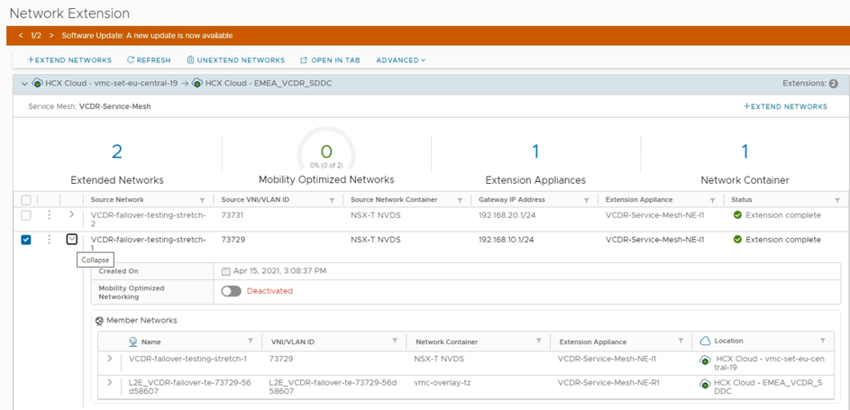
Figure 76: VMware HCX extended networks steady state.

Figure 77: Unextending the VMware HCX extended network.
- Select to make the unextended network(s) routable or leave as disconnected. If you make the network routable, there will be route advertisement across the VPN until it is disabled.

Figure 78: Using VMware HCX to unextend a network.

Figure 79: Using VMware HCX to unextend a network and connect the segment to the edge router.

Figure 80: Confirmation that Extend Segment 1 is removed.
- Disable the VPN connection and ensure that no routes are being learned across the tunnel now.

Figure 81: VPN is disabled and BGP is down.

Figure 82: No routes are being learned after disabling the VPN.
- If you left the network as disconnected, update it to a routed network in the destination SDDC.

Figure 83: Extended Network 1 shows as disconnected in steady state.

Figure 84: Extended Network 1 becomes a routed network after being unextended.

Figure 85: The segment is now routed in the SDDC.
- Execute the DR test from the VMware Cloud Disaster Recovery runbook. The DR plan network can match the failover and test as we are using the same network and no IP change steps are required.
![]()
Figure 86: Test DR plan.
- Confirm that the recovered VM has retained its production IP address.
Figure 87: Recovered workload confirming IP address.
- The recovered VM is able to communicate with other local routed subnets in the SDDC.
Figure 88: Recovered workload confirming connectivity to other VMware HCX extended segments.
- The recovered VM is not able to communicate with other remote subnets in the source or extended subnets.

Figure 89: Connectivity to routed segments over the VPN are unavailable.
Test scenario 3: Performing a test recovery into an isolated network with the same IP address

Figure 90: Performing a test recovery into an isolated network with the same IP address.
Scenario overview
In this DR test, we will be recovering the in-scope virtual machine(s) in the recovery SDDC. During a DR test, a copy of the virtual machine is recovered into the recovery SDDC from a snapshot of choice without impacting the production VM. In this test, the recovered virtual machines will be landed in an extended segment (Segment 2) in the SDDC, and the VMware Cloud Disaster Recovery DR plan will not change the recovered VM’s IP address. We are also retaining the site-to-site VPN connection during the test but are keeping the stretched subnet as a disconnected subnet to avoid a routing conflict.
For our example, we will be recovering a recovery point for VM2a into Stretched Segment 2. The virtual machine will retain its production IP address; however, the recovery segment is disconnected from production and Segment 2 network is not externally routable.
Before you begin
The following steps were used to simulate the testing of failover and recovery of services as previously described. Be sure to configure appropriate firewall rules, network segments, NAT rules (etc) as much as possible in advance to minimize the necessary effort during an actual outage.
In an actual test of your VMware Cloud DR Plan your steps may vary.
- VMware HCX managers must be able to communicate to perform extend/unextend operations.
- When disabling and then re-enabling VPN connectivity, give VMware HCX time to reestablish communications before attempting network extend/unextend operations (you may receive an error in the extension dialog, if not).
- By default, unextending a network will leave the remote network disconnected.
- Note: Virtual machines may only communicate with others on the same segment (unless a customer-managed virtual machine routing appliance is deployed to the segment).
- Distributed firewall rules can be used to further restrict VM traffic.
Execution summary
- Enable the VPN (if not already).
- Unextend the network. Do not connect the cloud router (segment will remain in a disconnected state).
- If running Mobility Optimized Networking, make sure to change the unextended network to disconnected.
- Run the failover test using the existing IP address; target segment is disconnected.
- Clean up the test.
- Extend the network from the source.
Test results
Virtual machines keep their IP addresses, VMs in the same subnet in the recovery SDDC can communicate to each other. However, they can’t communicate to other network segments, and their default gateway remains down. The network segment also is not advertised across the VPN or ENI connection, so no external traffic can reach the disconnected segment and virtual machines within it.
Steps to replicate test
- Validate the DR plan to ensure the failover and test mapping land the virtual machines in the appropriate production network that is currently extended and remove any IP address change/update rules. Note: You can still use the IP address rules to update DNS or default gateway addresses if custom values are needed during failover, or you want to use a virtual machine/appliance router in the recovered segment.

Figure 91: The DR runbooks have the same destination virtual network mapped for test and failover.

Figure 92: The DR plan does not change the IP address of the VMs.
- Unextend the segment(s) that the virtual machines will be landing in during the test.

Figure 93: VMware HCX extended networks steady state.

Figure 94: Unextending the VMware HCX extended network.
- Ensure to not connect the unextended network to the edge gateway so it remains a disconnected network after the unextend, and wait for the unextend to successfully complete.

Figure 95: Do not connect the network to the cloud edge gateway; leave it disconnected.

Figure 96: Confirmation that Extend Segment 2 is removed.
- Verify the unextended network is still a disconnected network.

Figure 97: Network Segment 2 remains disconnected type.
- Execute the DR test.
![]()
Figure 98: Test DR plan.
- After the recovery, the recovered VM2a has retained its production IP address and is able to communicate to the other virtual machine, VM2b, on the local segment.
Figure 99: The virtual machine has retained its production IP address post recovery.
Figure 100:Recovered VM can communicate with the other VM on the same segment.
- We can also verify that the recovered virtual machine is not able to reach a local gateway address of .1 as the network is now a disconnected network, and it is also not able to reach any other subnets/segments locally or across the VPN tunnel.

Figure 101: No local gateway or remote communication for the recovered VM.
Conclusion
VMware Cloud Disaster Recovery and VMware HCX provide a powerful set of capabilities to deliver fast, simple and cost-effective recovery capabilities using VMware Cloud on AWS. Workloads may be recovered quickly using the built-in orchestration capabilities of VMware Cloud Disaster Recovery. The target recovery site may be pre-provisioned or may be built on demand as part of your DR plan. Workload network configuration may be modified to meet the target network addressing scheme, or if using VMware HCX, the network configuration may be left intact, allowing the workload to retain existing addressing on a layer-2 adjacent network.
Together, VMware Cloud Disaster Recovery and VMware HCX dramatically simplify the architecture and execution of both disaster recovery testing and failover.
Unsupported Configurations and Scenarios
Migrated VM and xENI connected VPC private IP addresses
- Traffic between Mobility Optimized Networking-enabled migrated virtual machines and connected VPC private IP addresses.
Migrated VM and multitenant/CDS networks (VMs on tier 1 compute gateways in the same SDDC)
- Traffic between Mobility Optimized Networking-enabled migrated virtual machines across multitenancy VMware Cloud Director™ service boundaries.
Migrated VM and other SDDC VMs (over VMware Managed Transit Gateway/VMware Transit Connect™)
Traffic between Mobility Optimized Networking-enabled migrated virtual machines and virtual machines in other SDDCs (traffic over private VMware Transit Connect). MON-enabled networks are not advertised over Direct Connect connections, or over Transit Gateway / Transit Connect connections.
Considerations using VMware HCX Mobility Optimized Networking
Note: The use of HCX Mobility Optimized Networking is not currently supported generally for disaster recovery use cases, nor specifically with VMware Cloud Disaster Recovery. Networks configured for use with HCX Mobility Optimized Networks are supported as virtual machine networks in VMware Cloud on AWS, but not for use as recovery networks when used with VMware Cloud Disaster Recovery.
Migrated VM and extended networks in the SDDC with Mobility Optimized Networking disabled
Traffic between Mobility Optimized Networking-enabled migrated virtual machines to virtual machines on extensions without Mobility Optimized Networking is not optimized.
Migrated VM and SDDC management networks
Traffic between Mobility Optimized Networking-enabled migrated virtual machines and the SDDC management networks is not optimized.
Migrated VM with multiple vNIC (Mobility Optimized Networking functionality on secondary vNICs) with HCX versions prior to HCX 4.5
Mobility Optimized Networking functionality is only supported for multiple vNIC with HCX 4.5 and later.
VMware Cloud on AWS SDDCs with route-based VPN connections to AWS VPCs
Mobility Optimized Networking-enabled migrated virtual machines are advertised to route-based VPN connections. If the connected environment is a VPC, it is subject to an inbound 100 route limit. Using Mobility Optimized Networking in this scenario is not supported.
HCX and Mobility Optimized Networking route or prefix limits:
- VPN from SDDC to VPC or TGW: There is a limit of 100 routes advertised over VPN, which includes MON-enabled stretched networks. Reaching the limit of 100 routes will transition the VPN to a down state.
- SDDC private VIF to DX: 16 segments + 3 mgmt subnets will be advertised from the SDDC out, and up to 100 prefixes may be advertised in to the SDDC. The 16 compute segments out can be scaled up to ~100, but does not / will not include MON-enabled stretched networks.
- SDDC group via Transit Connect (vTGW): 250 prefixes advertised from a single SDDC to the SDDC Group; 1000 routes maximum in the SDDC group; 100 static routes per vpc attachment, does not / will not include MON-enabled stretched networks.
- TGW / vTGW association to DX gateway: There is no automatic advertisement of routes or prefixes. Up to 20 prefixes may be defined by the customer - which can include summary routes covering multiple networks in the SDDC group, does not / will not include MON-enabled stretched networks.
About the authors
Eskander Mirza has years of experience as an IT leader within the private and public sectors, including consulting and delivering technology solutions for his customers. Eskander now spends his time in presales leveraging his previous experience, paving the path to the cloud and infrastructure and application modernization for his customers. Eskander has extensive technical background in virtualization, storage, disaster recovery, information security, and hybrid and public cloud infrastructure, and was part of a very successful technology company, Datrium, which was acquired by VMware.
Tom Twyman is a senior staff cloud solutions architect for VMware, focused on VMware Cloud on AWS. For the past 25 years, Tom has worked as a consultant, trainer and systems engineer, working with businesses large and small to solve critical business issues through careful implementation of technology. Since joining VMware in 2007, he has specialized in virtualization and cloud technologies with extensive experience as a technical customer advocate. Tom has held multiple strategist, program lead, and architect roles to deliver complex software-defined data center architectures, both on premises and in the cloud.