
Global Load-Balancing for VMware Multi-Cloud SDDC Using Avi
Summary
AVI GSLB provides load balancing of applications across multiple geographically dispersed locations (typically, multiple data centers and/or public clouds), while providing centralized configuration, application monitoring, and analytics.
However, most of the AVI GSLB deployments was done for applications hosted in the public-Cloud with Public-IP access (AWS, GCP, Azure or OCI).
This article was created to show that AVI Global load-balancing can be used to load-balance application workloads with Private-IPs, hosted in multiple VMware SDDCs in public-Cloud providers (i.e,. AWS, Google, Azure and Oracle Cloud).
Users attempting to access a particular application will be routed using advanced AVI load-balancing algorithm to a VMware private SDDC.
In this paper, we have two sections. Section 1 will walk-you through the architecture of AVI GSLB for multi-cloud VMware SDDC and Section 2 will walk-you through the implementation of AVI-GSLB multi-cloud architecture in details and explain all the necessary steps required for a successful implementation.
Overview
It is important to start by explaining how AVI GSLB works at a high level, once this is out of the way, I will explain the architecture of the public and private Cloud environments required to implement a successful Multi-Cloud AVI GSLB deployment.
AVI GSLB
AVI GSLB provides load balancing of applications across multiple geographically dispersed locations, while providing centralized configuration, application monitoring, and analytics.
What is GSLB?
Global Server Loading Balancing (GSLB) is the act of balancing an application’s load across instances of the application that have been deployed to multiple locations (typically, multiple data centers and/or public clouds). Application load at any one of those locations is usually managed by a “local” load balancer, which could be AVI Vantage or a third-party ADC solution.
GSLB is usually implemented to achieve one or more of the following goals for an application:
- Provide optimal application experience to users/clients who are in geographically distributed areas
- Offer resilience to loss of a data center or a network connection
- Perform non-disruptive migration to or addition of another data center
GSLB High-Level Functionality
To achieve these goals AVI GSLB performs the following functions:
- It chooses the location (Data Center/Cloud) to which to steer the client's requests
- It monitors health of the virtual services so that it can choose the best location (i.e., rule out unhealthy ones)
- It synchronizes configuration and state across GSLB sites, so that #1 and #2 can continue despite certain failures
Functions 2 and 3 are performed by AVI GSLB in a fashion that is totally opaque to end-users. AVI uses the Domain Name System (DNS) for providing the optimal destination information to the user clients. When a client (typically a browser) performs a DNS query on fully qualified domain names (FQDNs), AVI GSLB responds with the IP address (VIP) of the optimal application instance. The optimal address can and will change based on the load balancing algorithm, health of the application instances, and the location of the clients.
How AVI GSLB Works
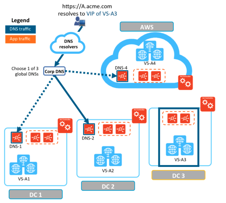
As an example, refer to the setup in the following diagram:
- AVI Vantage is running in four locations (GSLB sites), three on-premises and one in AWS. Each site has its own AVI Controller cluster (represented by a single Controller icon).
- Application “A” has virtual services running in all four locations. These virtual services are identified by VS-A1 through VS-A4.
- Three of the four locations (DC-1, DC-2, and AWS) have global DNS services (DNS-1, DNS-2, and DNS4) that are synchronized. They are all equally authoritative for the subdomain A.acme.com.
- The fourth site (DC3) does not run a global DNS service and therefore can’t provide request-steering information.
Now that we understand how AVI GSLB work, we can now apply the same concepts for workloads hosted in VMware SDDCs, however, before diving in, let’s first discuss the multi-cloud environment that we will apply this architecture to. For more details, please read the next section.
The VMware Multi-Cloud Lab
The VMware Multi-Cloud Lab is a world class lab connecting multiple Public Cloud providers together.
It is a collection of public cloud platforms and VMware services that are meant to drive multi-cloud and hybrid cloud reference architectures, showcase VMware multi-cloud capabilities in practice and drive innovation via BU collaboration or feedback. Due to the broad range of platforms and services available in the lab, almost any use case or solution is possible, however, we limit the use cases to be focused on multi-cloud or hybrid-cloud. A few examples are below.
- Deploying or operating Hybrid-Cloud environment (e.g. VMC on AWS on Premises, GCVE + VMC on AWS, AVS + GCVE, etc...)
- Cloud migration (premises to VMware Cloud on AWS)
- Managing a multi-cloud application with Wavefront
- Deploying a multi-cloud application using Tanzu on EC2 and AVS
One of the unique features in the multi-cloud lab is its advanced subnet routing between the different cloud providers, in other words, the lab administrators have granular control of which subnets are permitted between different cloud platforms.
As mentioned above, the VMware multi-cloud lab hosts multiple VMware SDDCs, VMC on AWS, Google Cloud VMware Solution, Azure Cloud VMware Solution and Oracle Cloud VMware Solution. This VMware SDDCs host the VMware Workloads which are used to test AVI GSLB.
Each SDDC has the basic VCF building blocks, vCenter, NSX, HCX, vSAN, ESXi hosts.
The following diagram shows the Multi-Cloud architecture.
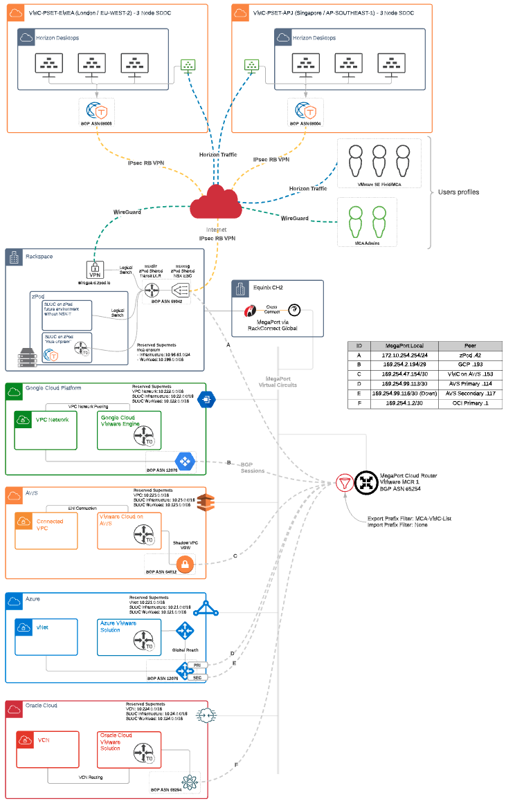
The Multi-Cloud Router (Mega-Port)
If you are wondering how the VMware SDDCs communicating with each other, then it is time to talk about the Mega-Port Router (MCR). However, before explaining the MCR method of operation, it is important to know that you can use multiple different vendors to facilitate the communication between your Cloud SDDCs, the multi-cloud lab is using Mega-Port for this purpose.
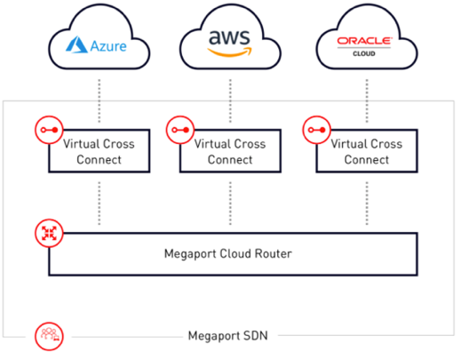
MCR Overview
The MCR is a managed virtual router service that establishes Layer 3 connectivity on the worldwide Megaport software-defined network (SDN). MCR instances are preconfigured in data centers in key global routing zones. An MCR enables data transfer between multi-cloud or hybrid cloud networks, network service providers, and cloud service providers.
An MCR instance is not physically cross-connected like a Port in the Megaport network. However, it can host Layer 2 VXC connections just like a physical Port and it can extend to any other Port in the Megaport network or another MCR.
How it works
An MCR joins two or more independent Virtual Cross Connect (VXC) services into a single routing domain, providing connectivity between all the VXCs attached to the MCR.
Without physical infrastructure, you can leverage cloud-to-cloud networking, private peering between leading public Cloud, IaaS, and SaaS providers, and direct connectivity to any provider on the Megaport Software Defined Network (SDN). There is no need to own and maintain equipment. MCR removes the complexity of getting connected at Layer 3 and opens new possibilities for virtualized networking.
You can use an MCR instance either with or without a physical Port in the Megaport network. If you want to configure multi-region deployments with a single cloud service provider (CSP), or a multi-cloud deployment with multiple CSPs, MCR can enable both functionalities. Combining MCR functionality with a physical Port in the Megaport network has added benefits:
- Reduced latencies by enabling direct connections among cloud providers.
- Inter-region or inter-cloud connectivity to control and localize traffic.
Section 1: AVI-GSLB SDDC Architecture
Before diving into the details, let’s start with the following architecture diagram which illustrates a detailed view of the AVI-GSLB multi-cloud architecture.
I will break down the architecture into its basic building blocks in the next few sections of this document.
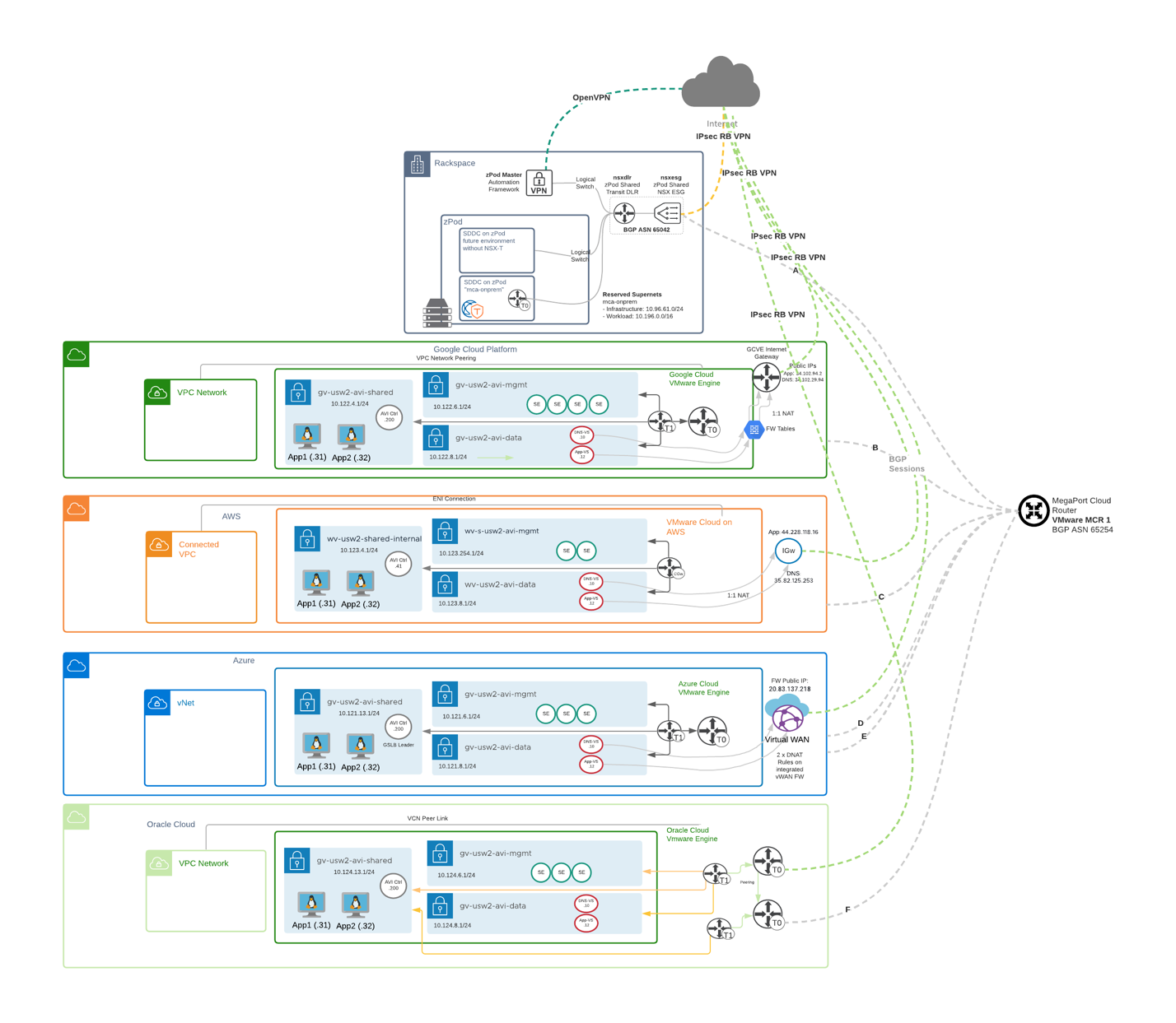
Each SDDC in the above diagram has few components that build the SDDC architecture, in the next few lines I will share the required components that are used to build the architecture.
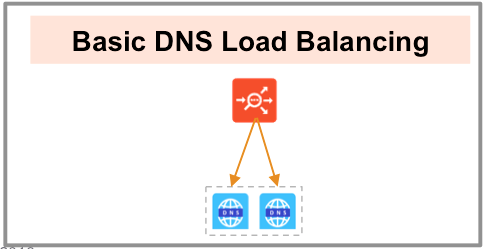
DNS Load Balancing
Let’s now dive into the concept of DNS load balancing, this is the concept used by AVI for GSLB.
Avi Service Engines proxy DNS requests to a back-end pool of DNS servers. A virtual service with a System-DNS (or similar) application profile is defined as usual. For this, a pool of back-end servers loaded with DNS software packages must be assigned.
Avi DNS runs a virtual service with System-DNS application profile type and a network profile using per-packet load balancing.
Referring to the diagram below, a DNS service — represented in green— is hosted on the leftmost Service Engine. The DNS virtual service responds to DNS queries if there is a matching entry. If a matching entry is not found and if pool members are configured, the DNS virtual service forwards the request to the back-end DNS pool servers (represented in blue).
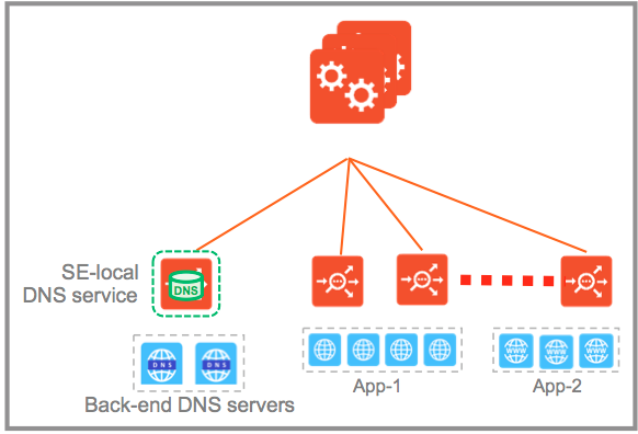
An Avi DNS virtual service can act as an authoritative DNS server for one or more subdomains (zones) and all analytics and client logs are supported.
Deployment Scenario – Authoritative Name Server for Subdomain (Zone)
In this scenario, the corporate name server delegates one or more subdomains to the Avi DNS service, which in turn acts as an authoritative DNS server for them. In the example shown below, avi.mcsa.cloud and mcsa.cloud are the subdomains. Typically, the corporate name server will have a NS record pointing to the Avi DNS service. Client queries for these subdomains are sent directly to Avi Vantage, whereas all DNS requests outside of mcsa.cloud are instead sent to the external “.cloud” name server.
For load balancing to work, the corporate DNS servers are pooled together and exposed by an Avi SE group as a single, scaled DNS service
All clients queries for the subdomains that are sent directly to AVI Vantage are NAT’d at each Cloud provider edge (AWS, GCP, Azure & OCI) and forwarded to DNS Virtual Service inside each VMware SDDC.
Now, let’s apply this load-balancing concept to a multi-Cloud architecture, however, let me walk you through the building block of the architecture for each SDDC.
The building blocks of the Multi-Cloud Architecture
If you look deeply into the architecture diagram at the beginning of section 1, you will notice some common components in each SDDC, you will also notice some differences as well, let’s discuss this in more details in the next section.
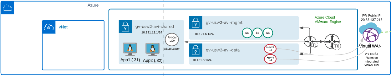
Azure VMware Solution building Blocks:
- VMware SDDC - AVS
- vCenter
- vSAN
- NSX
- Management Network for AVI Service Engine Management – wv-s-usw2-avi-mgmt (10.121.6.1/24)
- Data Network for AVI Virtual Services (DNS and Application VIPs) – wv-usw2-avi-data (10.121.8.1/24)
- Shared Network for AVI Controller and application hosts – wv-usw2-shared-internal (10.121.13.1/24)
- HCX for workload mobility – Not a requirement for AVI GSLB
- AVI Controller – GSLB Leader – 10.121.13.200
- AVI Service Engines
- AVI Virtual Service
- DNS-VS – 10.121.8.1.10
- Application-VS – 10.121.8.12
- Two copies of an application running on two different ESXi hosts.
- App1 – 10.121.13.31
- App2 – 10.121.13.32
- Azure
- Azure vWAN** - Please refer to future work section for more details.
- Azure Firewall
- Azure Firewall Manager
- Firewall Tables
- Destination NAT
- Azure Internet Gateway
- Azure VPC
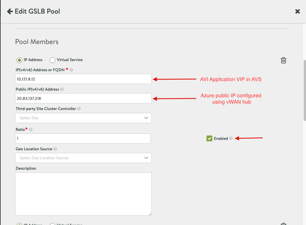
- Azure Public IP Address (20.83.137.218)
- Global DNS Configuration – Route53 - http://global.demoavi.mcsa.cloud/
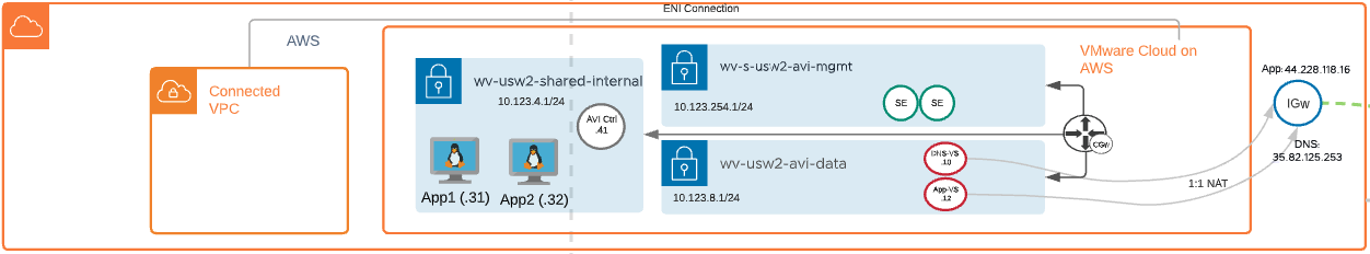
VMware Cloud on AWS:
- VMware SDDC - VMC
- vCenter
- vSAN
- VMC Networking and Security
- Segments
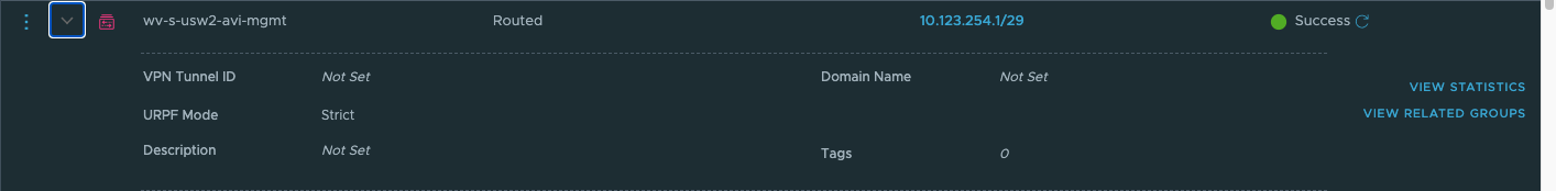
- Management Network for AVI Service Engine Management – wv-s-usw2-avi-mgmt (10.123.254.1/24)
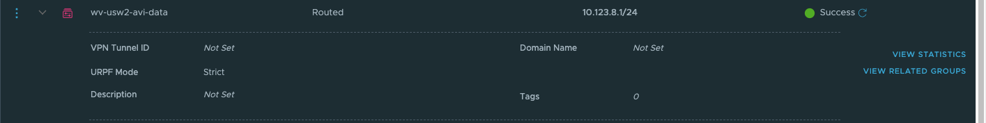
- Data Network for AVI Virtual Services (DNS and Application VIPs) – wv-usw2-avi-data (10.123.8.1/24)
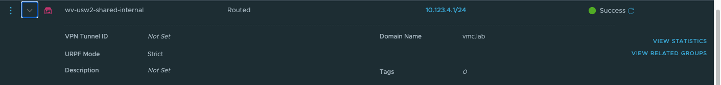
- Shared Network for AVI Controller and application hosts – wv-usw2-shared-internal (10.123.4.1/24)
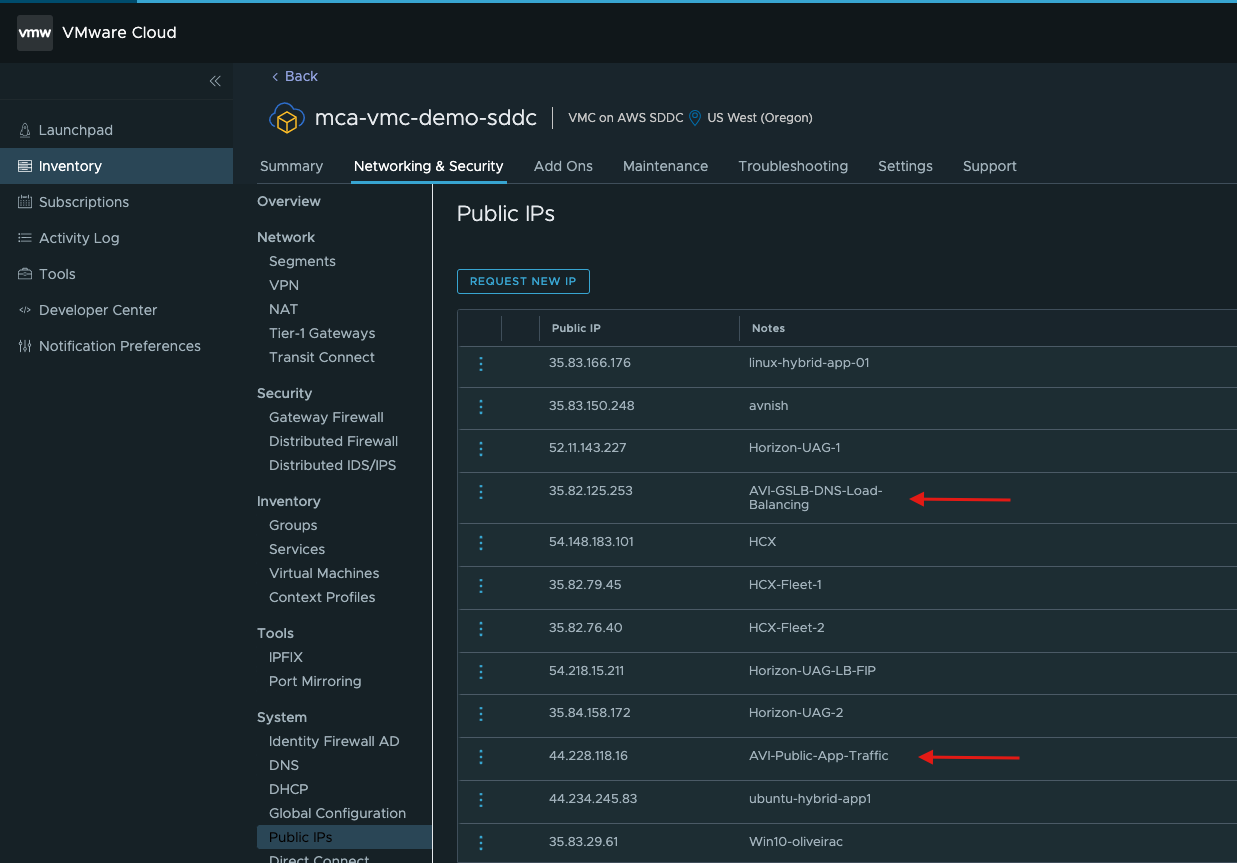
- Public IPs
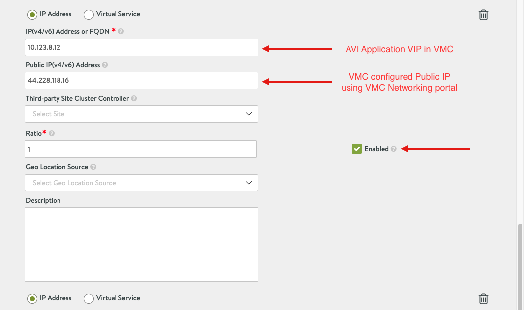
- AVI-Public-App-Traffic – 44.228.118.16
- AVI-GSLB-DNS-Load-Balancing – 35.82.125.253
- Security – Gateway Firewall
- AVI-DNS-Inbound – Allow traffic to AVI-DNS-VS for the following services (ICMP, DNS-UDP and DNS)
- Internet Inbound – Allow internet inbound traffic for AVI-DNS-VS and Applications. Use Inventory Group configuration for better management of traffic.
- HCX for Workload mobility – Not a requirement for AVI GSLB
- AVI Controller – 10.123.4.41
- AVI Service Engines
- AVI Virtual Service
- DNS-VS – 10.123.8.1.10
- Application-VS – 10.123.8.12
- Two copies of an application running on two different ESXi hosts.
- App1 – 10.123.4.31
- App2 – 10.123.4.32
- AWS
- Route53 for DNS management – Applies for all clouds.
- Global DNS Configuration – Route53 - http://global.demoavi.mcsa.cloud/
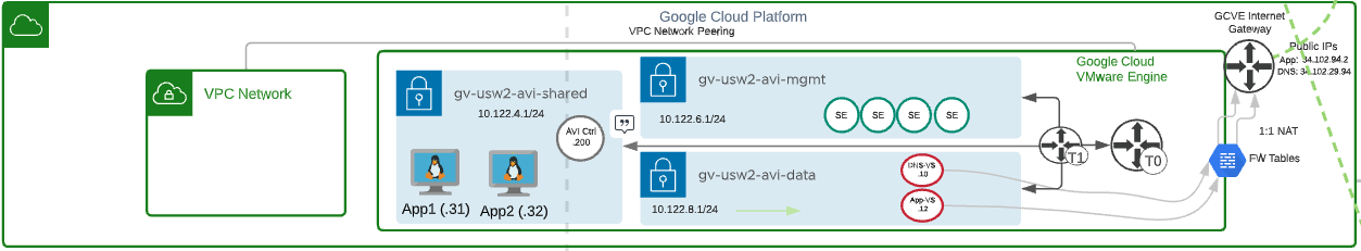
Google Cloud VMware Solution:
- VMware SDDC - GCVE
- vCenter
- vSAN
- NSX
- Management Network for AVI Service Engine Management – gv-usw2-avi-mgmt (10.122.6.1/24)
- Data Network for AVI Virtual Services (DNS and Application VIPs) – gv-usw2-avi-data (10.122.8.1/24)
- Shared Network for AVI Controller and application hosts – gv-usw2-shared-internal (10.122.4.1/24)
- HCX for workload mobility – Not a requirement for AVI GSLB
- AVI Controller – 10.122.4.200
- AVI Service Engines
- AVI Virtual Service
- DNS-VS – 10.122.8.1.10
- Application-VS – 10.122.8.12
- Two copies of an application running on two different ESXi hosts.
- App1 – 10.122.4.31
- App2 – 10.122.4.32
- GCvE internal Internet Gateway**
- Public IPs
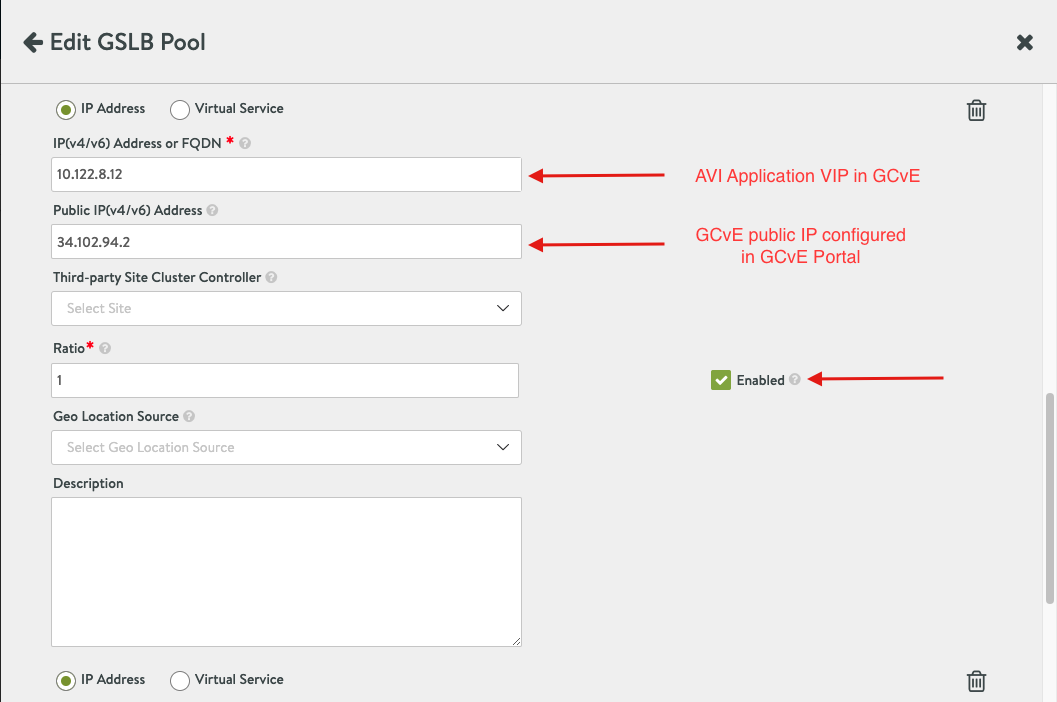
- Avi-app-public-ip – 34.102.94.2 (Google cloud does 1:1 Natting by default for public IPs to a private SDDC IP – 10.122.8.12 for application VIP)
- Avi-dns-ip – 34.102.29.94 (Nat’d to 10.122.8.10)
- Firewall Tables
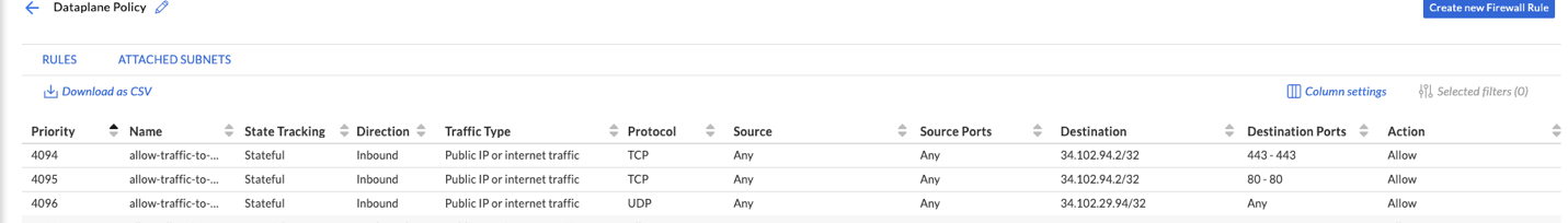
- Allow inbound TCP traffic to AVI from any source to 34.102.94.2/32 for Ports 443 and 80
- Allow inbound UDP traffic from any source to 34.102.29.94/32 for all ports
- Google Cloud
- Google Cloud VPC
- Global DNS Configuration – Route53 - http://global.demoavi.mcsa.cloud/
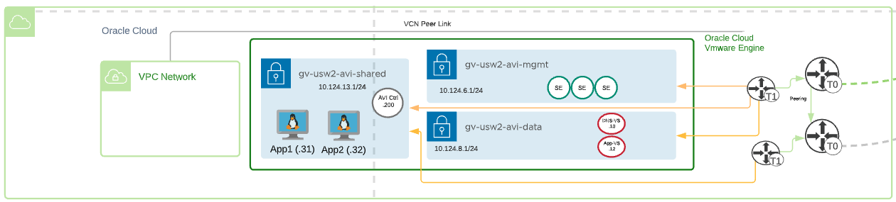
Oracle Cloud VMware Solution:
- VMware SDDC - OCVS
- vCenter
- vSAN
- NSX
- Management Network for AVI Service Engine Management – gv-usw2-avi-mgmt (10.124.6.1/24)
- Data Network for AVI Virtual Services (DNS and Application VIPs) – gv-usw2-avi-data (10.124.8.1/24)
- Shared Network for AVI Controller and application hosts – gv-usw2-shared-internal (10.124.13.1/24)
- HCX for workload mobility – Not a requirement for AVI GSLB
- AVI Controller – 10.124.13.200
- AVI Service Engines
- AVI Virtual Service
- DNS-VS – 10.124.8.1.10
- Application-VS – 10.124.8.12
- Two copies of an application running on two different ESXi hosts.
- App1 – 10.124.13.31
- App2 – 10.124.13.32
- Public IPs – WiP for this section
- Oracle Cloud – WiP for this section
- Global DNS Configuration – Route53 - http://global.demoavi.mcsa.cloud/
Section 2: AVI-GSLB SDDC Configuration Guide
Deploy AVI-GSLB on Azure Cloud VMware Solution
Before deploying AVI-GSLB we must fully deploy an AVI Controller and AVI Service Engines on AVS. The process of deploying AVI is straightforward and similar a typical AVI deployment on vSphere, I will walk you through the process once in this section and highlight any additional requirements on future sections.
The deployment architecture is discussed in an earlier section on this document, please reference it for more information.
Prerequisites
Role Requirement
The AVI Controller requires:
- The NSX Network Engineer role or higher
- VMware vCenter Permissions as defined in Roles and Permissions for vCenter and NSX-T Users (https://avinetworks.com/docs/latest/roles-and-permissions-for-vcenter-nsx-t-users/)
- You can use the cloudadmin user and credential provided for AVS. This user has a role which is a superset of the required permissions and is sufficient for the integration.
Content Library
The AVI Controller uploads the Service Engine image to the content library on the vCenter server and uses this to create new virtual machine (VM) every time a new Service Engine is required. The content library must be created on vCenter before configuring the NSX-T cloud. In the vCenter vSphere client:
- Navigate to Content Libraries.
- Click on Create.
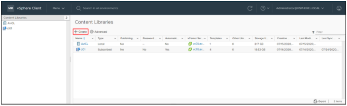
- The New Content Library wizard opens. In the Name and location page, enter the Name and select a vCenter Server instance for the content library as shown below:
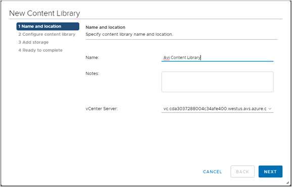
- Click on Next.
- In the Configure content library page, select Local content library.
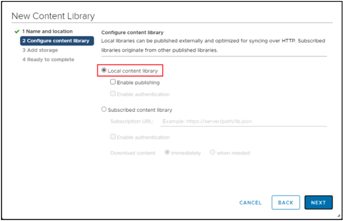
- Click on Next.
- In the Add storage page, select a datastorage location for the contents of the content library.
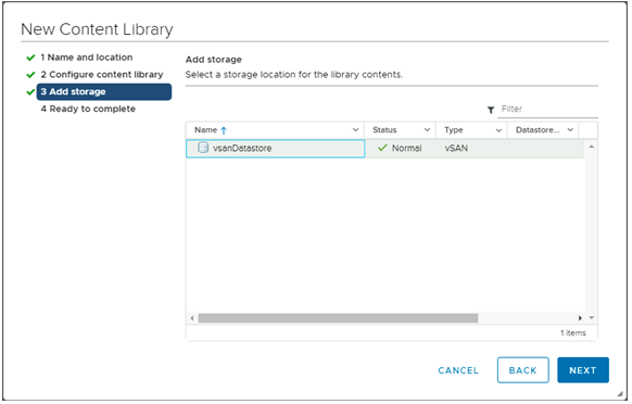
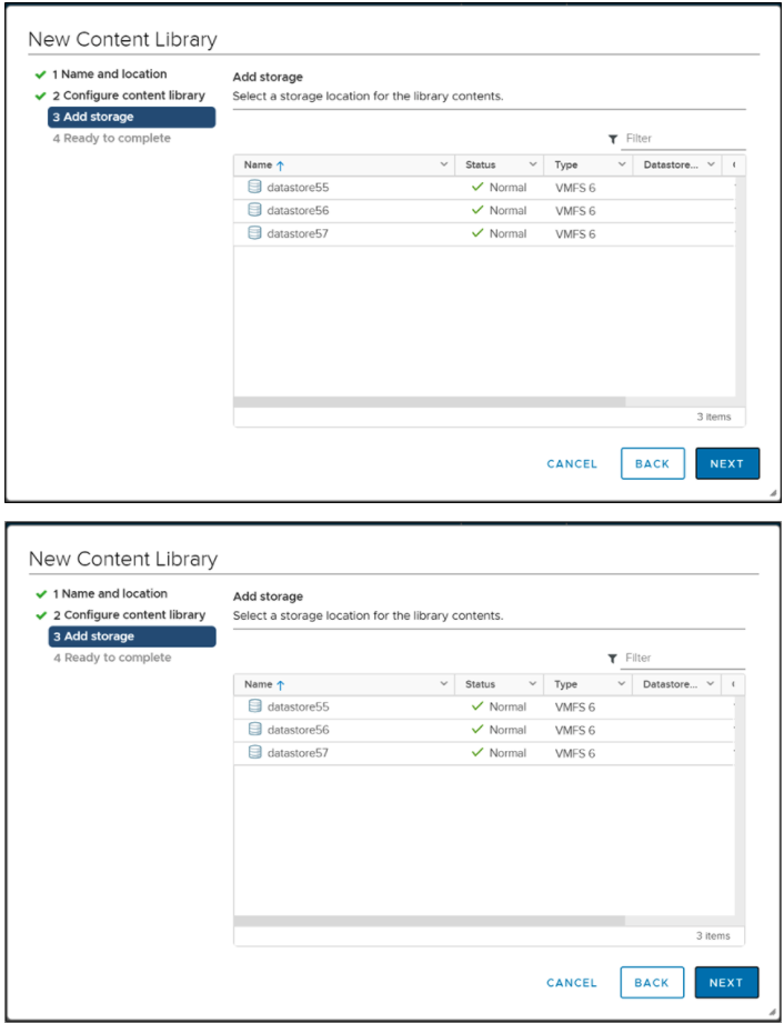
- Click on Next.
- In the Ready to complete page, review the details.
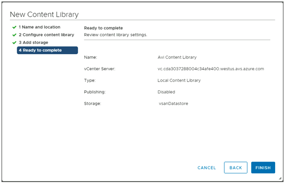
- Click on Finish.
Deploying the AVI Controller OVA
To deploy the AVI Controller OVA:
- Login to the vCenter server through a vCenter client, using the fully qualified domain name (FQDN).
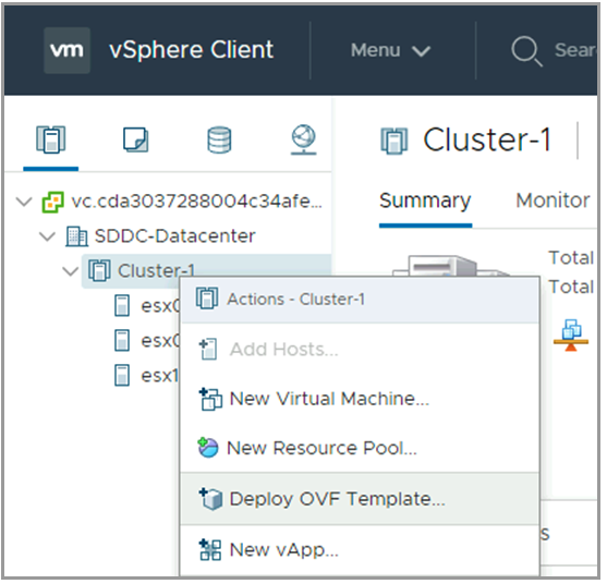
- From the File menu, select Deploy OVF Template.
- Select the controller.ova file from your local machine.
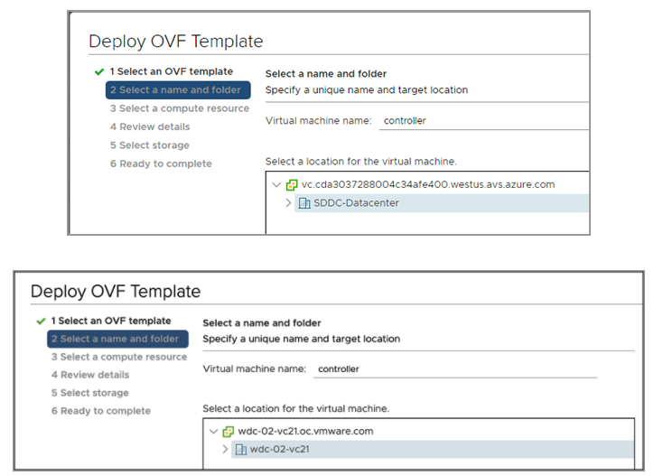
- In the Deploy OVF Template wizard, select the VM name and the location to deploy.
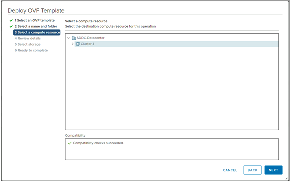
- Select the compute resource.
- Review the details.
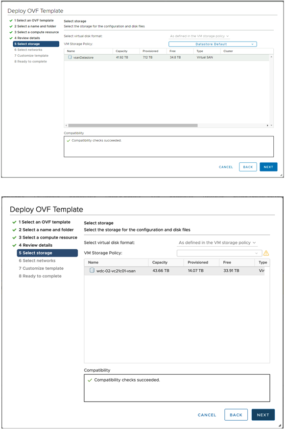
- Select storage.
- Choose a management network for the Avi Controller.
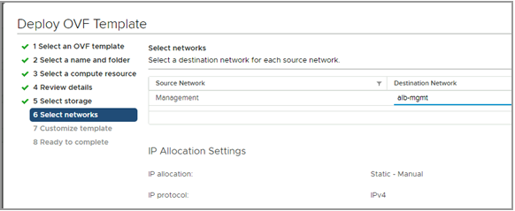
- Enter the management IP address, subnet mask and default gateway. In the case of DHCP, leave this field empty.
Note: Using static IP address is recommended for production setups.
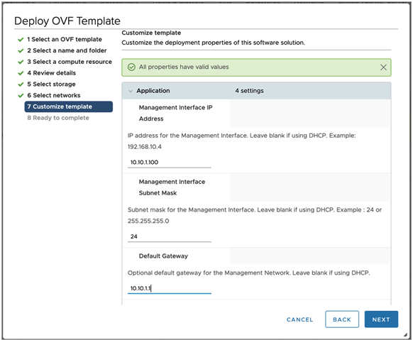
- Review the settings and click on Finish. After this, power on the virtual machine.
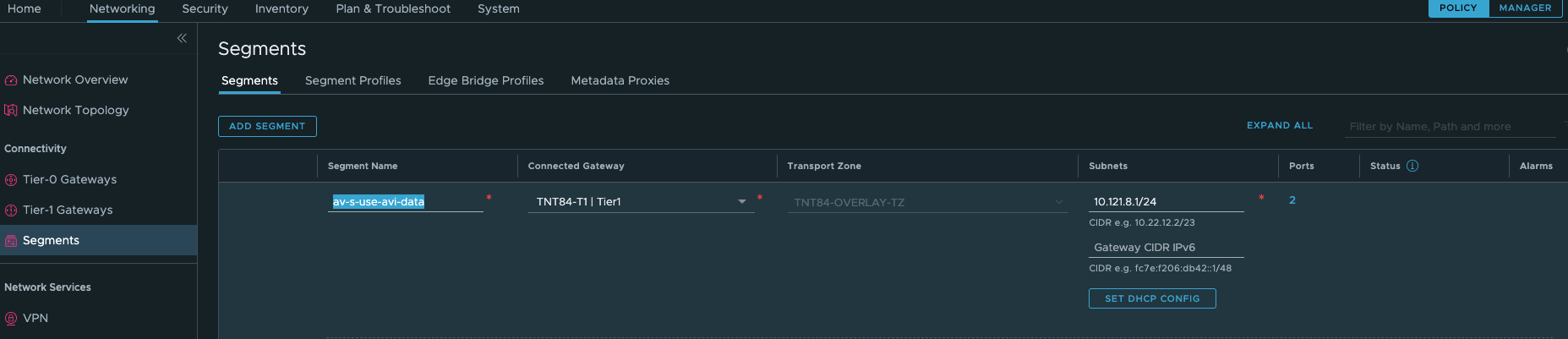
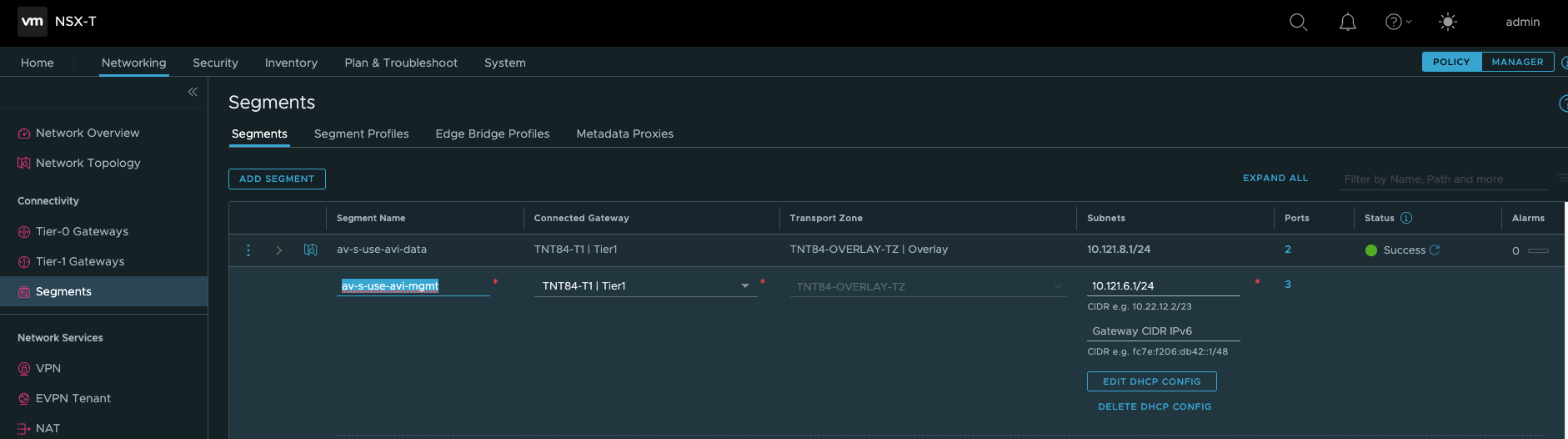
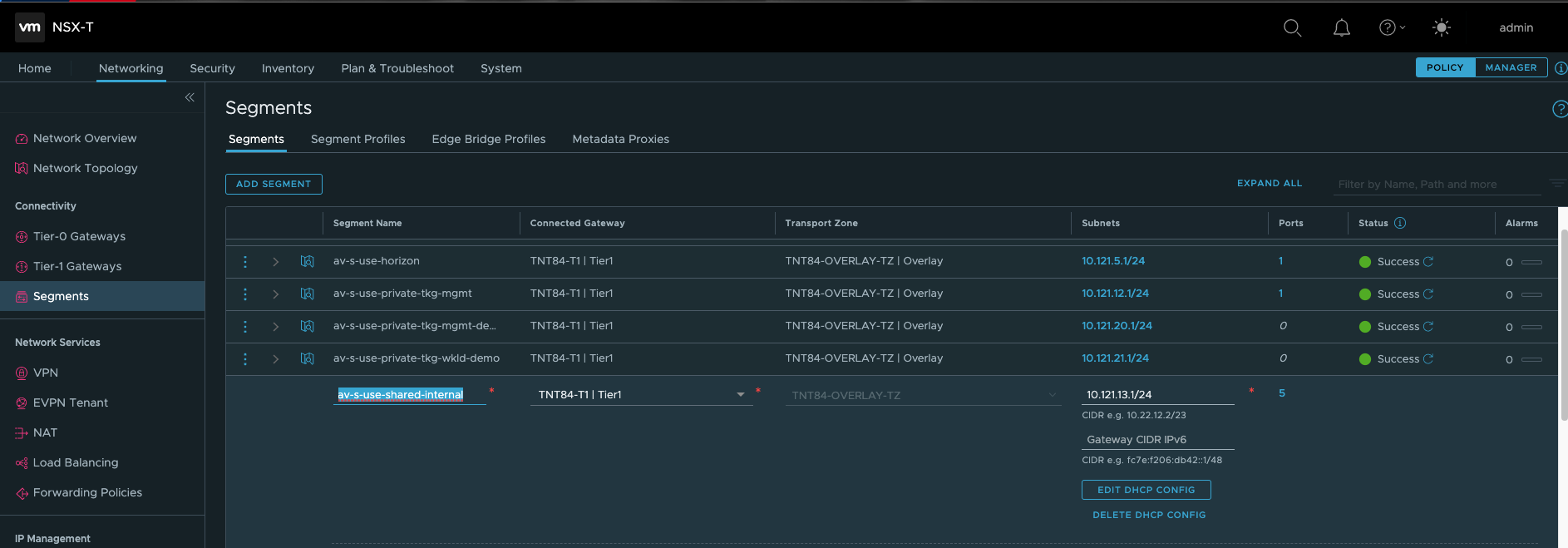
Configuring AVI Network Segments in NSX-T
Assuming your NSX-T is up and running for your Azure VMware Solution SDDC, you should be able to navigate to Networking > Segments and add your data, management and shared networks.
This is a very important step to allow proper traffic routing between your different AVI components.
Setting up the Avi Controller
This section shows the steps to perform initial configuration of the Avi Controller using its deployment wizard. You can change or customize settings following initial deployment using the Avi Controller’s web interface.
- To complete the setup, navigate to the Avi Controller IP via a browser.
Note: While the system is booting up, a 503 status code or a page with following message will appear, “Controller is not yet ready. Please try again after a couple of minutes”. Wait for about 5 to 10 minutes and refresh the page. Then follow the instructions below for the setup wizard.
- Enter the admin details as shown below:
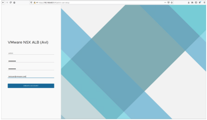
Note: This e-mail address is required for admin password reset in case of lockout.
- Enter the backup passphrase, DNS server information.
- Configure the Email/SMTP information.

- Click on Save.
Creating an NSX-T Cloud
To create an NSX-T cloud, log in into the Avi Controller and follow the steps given below:
Create Credentials
- In the Avi UI, Navigate to Administration > User Credentials.
- Click on Create.
- Provide a Name for the credential.
- Select NSX-T as the Credentials Type.
- Provide the NSX Username and Password
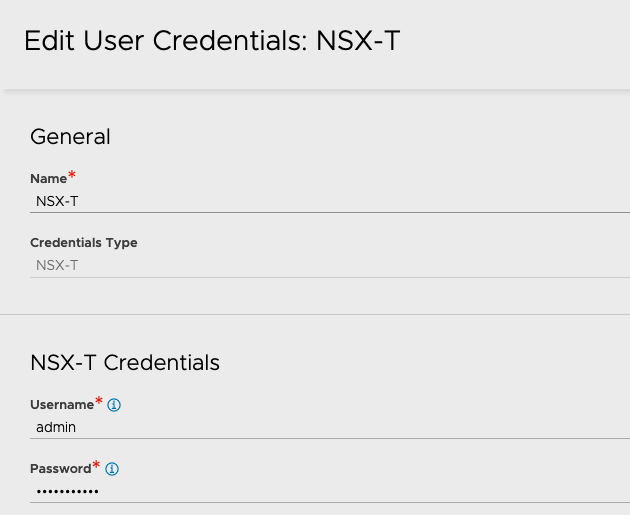
- Click on Save
Similarly, create the vCenter credentials.
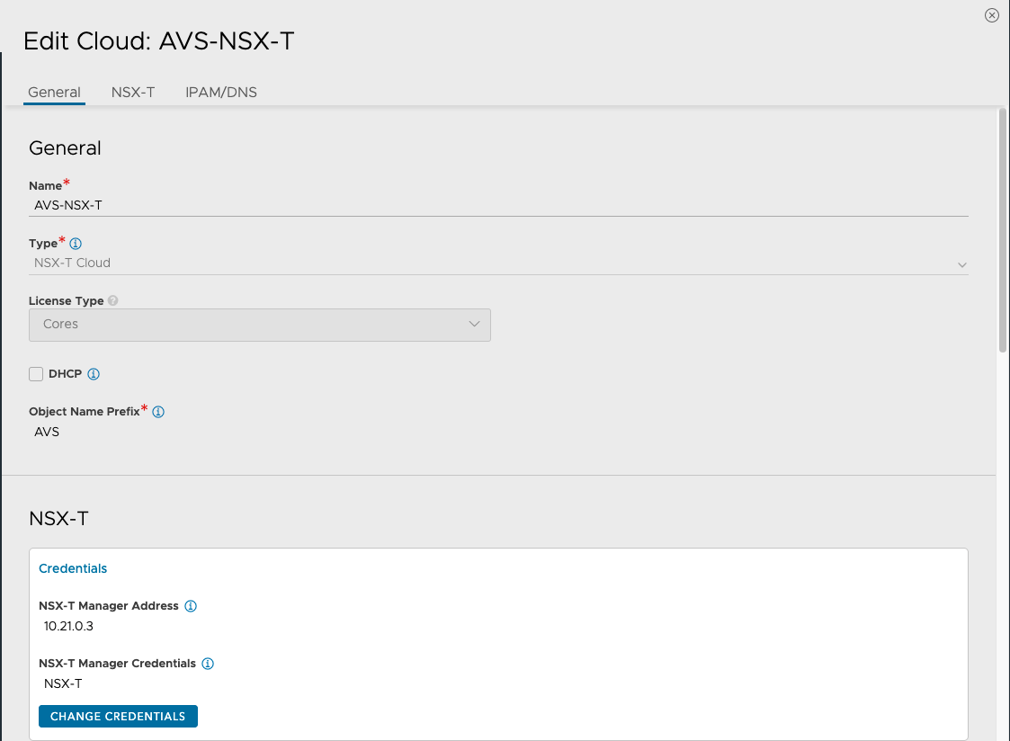
Configure the Cloud
To configure the cloud:
- Navigate to Infrastructure > Clouds.
- Click on Create and select the NSX-T Cloud.
- Enter the Name of the NSX-T cloud.
- Check the DHCP option if SE management segment has DHCP enabled.
- Enter a prefix string. The prefix string must only have letters, numbers, and underscore. This field cannot be changed once the cloud is configured.
- Enter the NSX-T manager hostname or IP address as the NSX-T Manager Address and select the NSX-T Manager Credentials.
- Click on Connect to authenticate with the NSX-T manager.
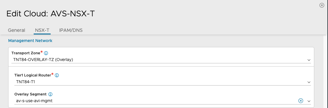
- Select the Transport Zone required from the drop-down.
- Under Management Network Segment, select the Tier1 Logical Router ID and Segment ID.
- Select the Tier-1 gateway and logical switch for VIP placement.
- Click on Add to select one more Tier-1 router and a connected logical segment for VIP placement.
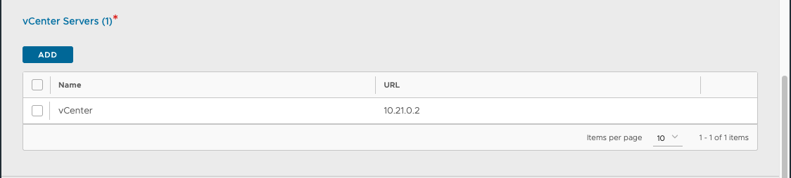
- Under vCenter Servers, click on Add.
- Enter the vCenter server Name and configure the credentials.
- Click on Connect.
- Select the Content Library and click on Done.
- Select the IPAM/DNS Profile, as required.
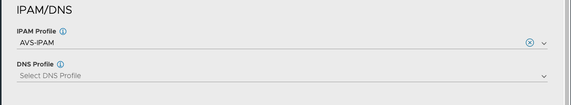
Note: you might need to go and create an IPAM and DNS profiles before going through the previous step
- Click on Save to create the NSX-T cloud.
The Cloud Connector Status will turn green, and the system is ready for creation of a virtual Service.
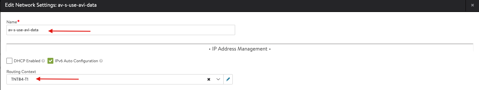
Configure Networks
- From the Controller UI, navigate to Infrastructure > Networks
- Select the cloud (AVS-NSX-T)
- Select Create
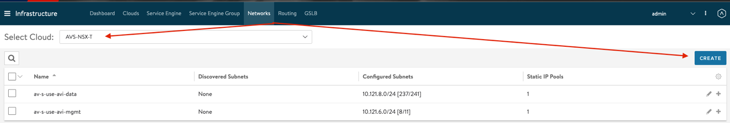
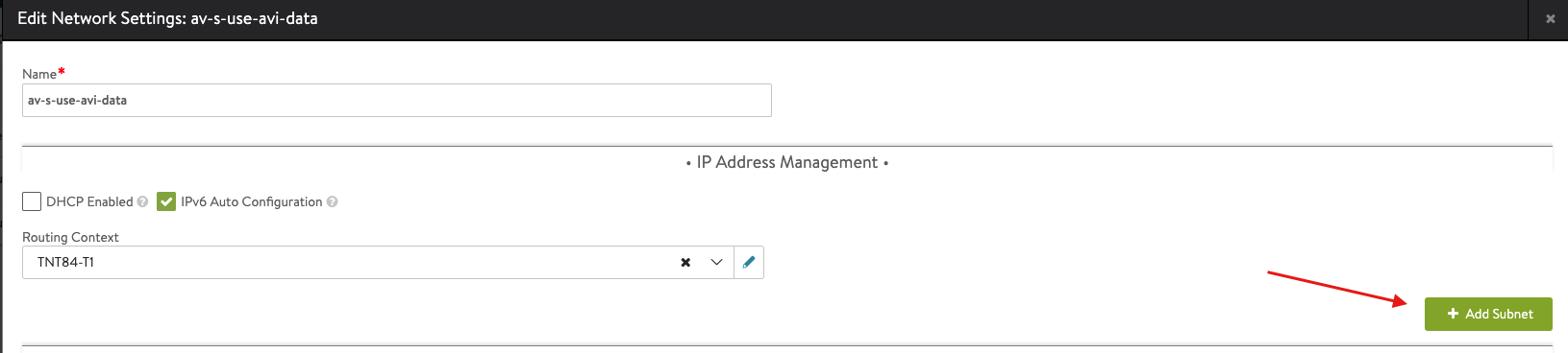
- Enter the details as per the following image
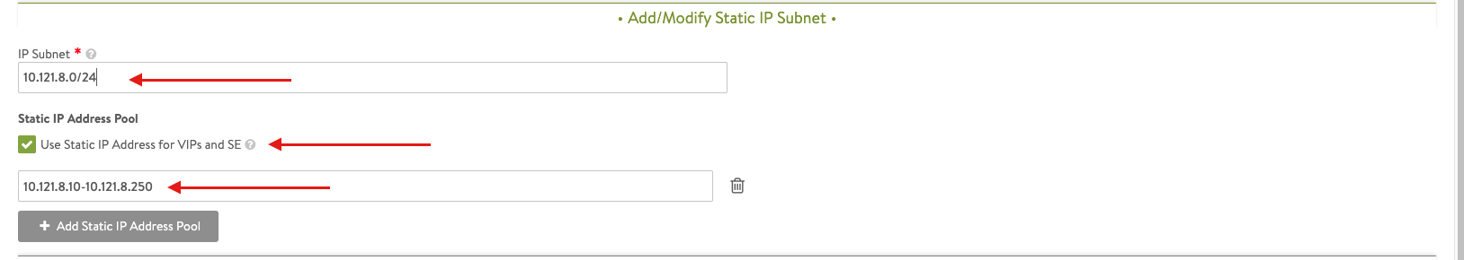
- Select Add Subnet and insert the following details
Apply the same previous steps to create the AVI management network.
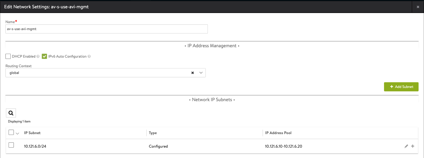
Note: The av-s-use-avi-data network will be used by AVI for application VIPs, the av-s-use-avi-mgmt will be used by AVI for the Service Engines
Creating Virtual Services (DNS and Application VIPs)
DNS Virtual Service
- From the Controller UI, navigate to Applications > Create Virtual Service (Advanced Setup).
- Select the cloud (AVS-NSX-T)
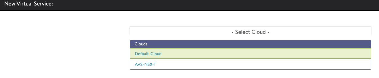
- Enter the details related to the VS IP, Pool members, Tier 1 Logical Router, etc.
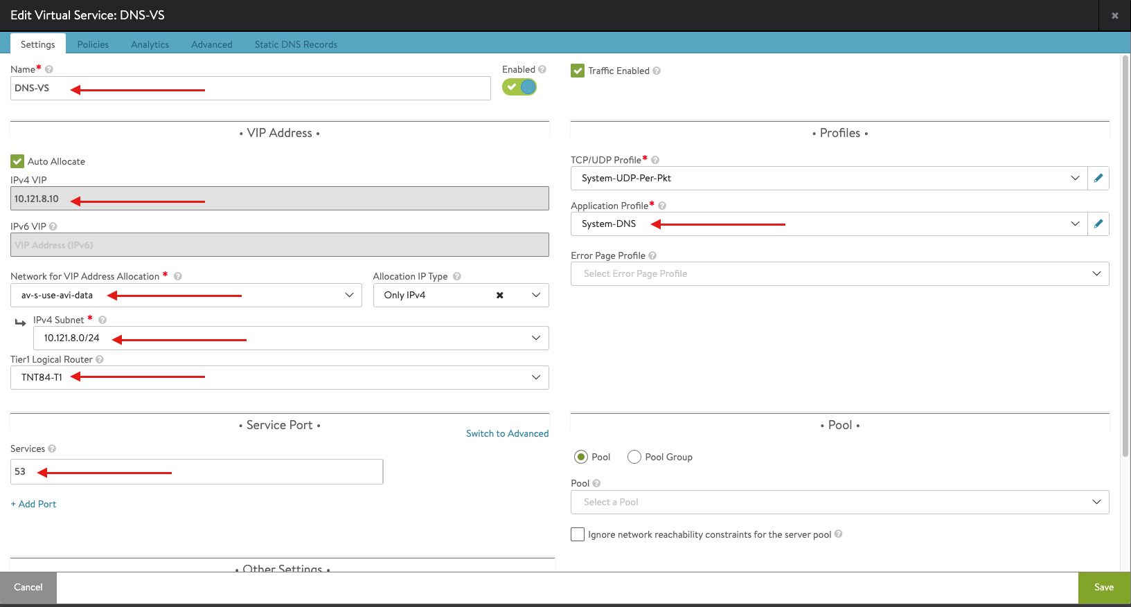
Note: you need to configure the DNS-SE group shown in the above snapshot, you can do sy by clicking on the pencil symbol associated with SE-Group and apply the following configuration.
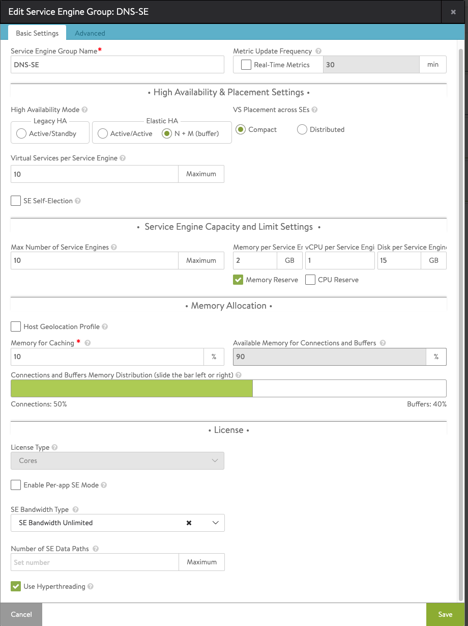
Once this is done, hit save and resume the configuration.
- click on Save to create the virtual service.
On successful creation of a Service Engine, the virtual service will come up and will be ready to process traffic.
Application Virtual Service
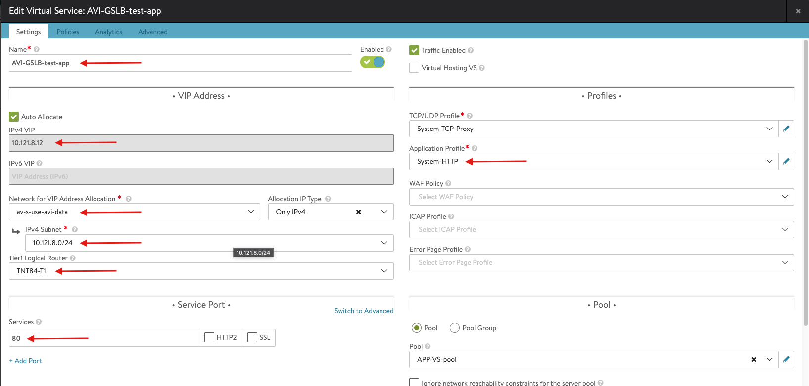
Go through the same steps to configure the application virtual service, however, apply the following configurations this time:
- Enter the details related to the VS IP, Pool members, Tier 1 Logical Router, etc. Note the pool configuration is show in the next screenshot.
- Create a Pool
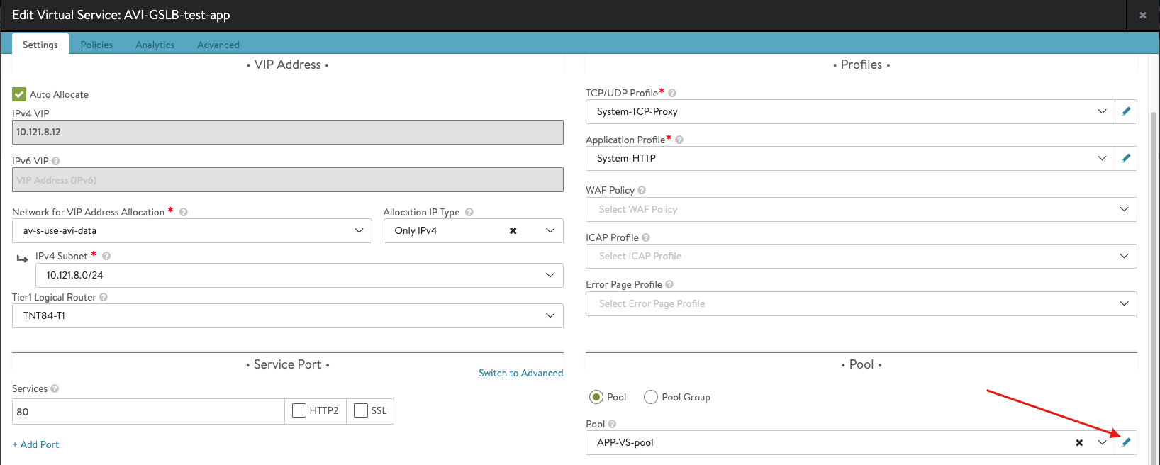
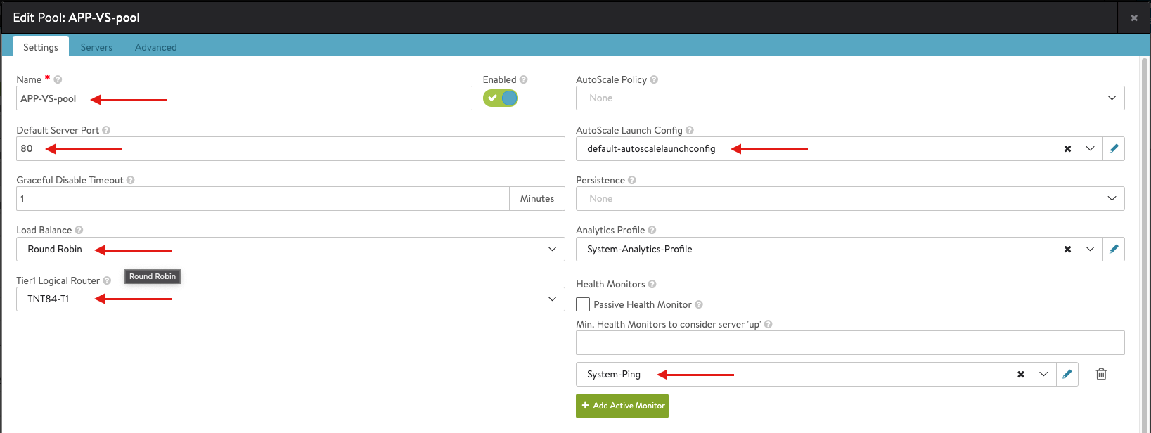
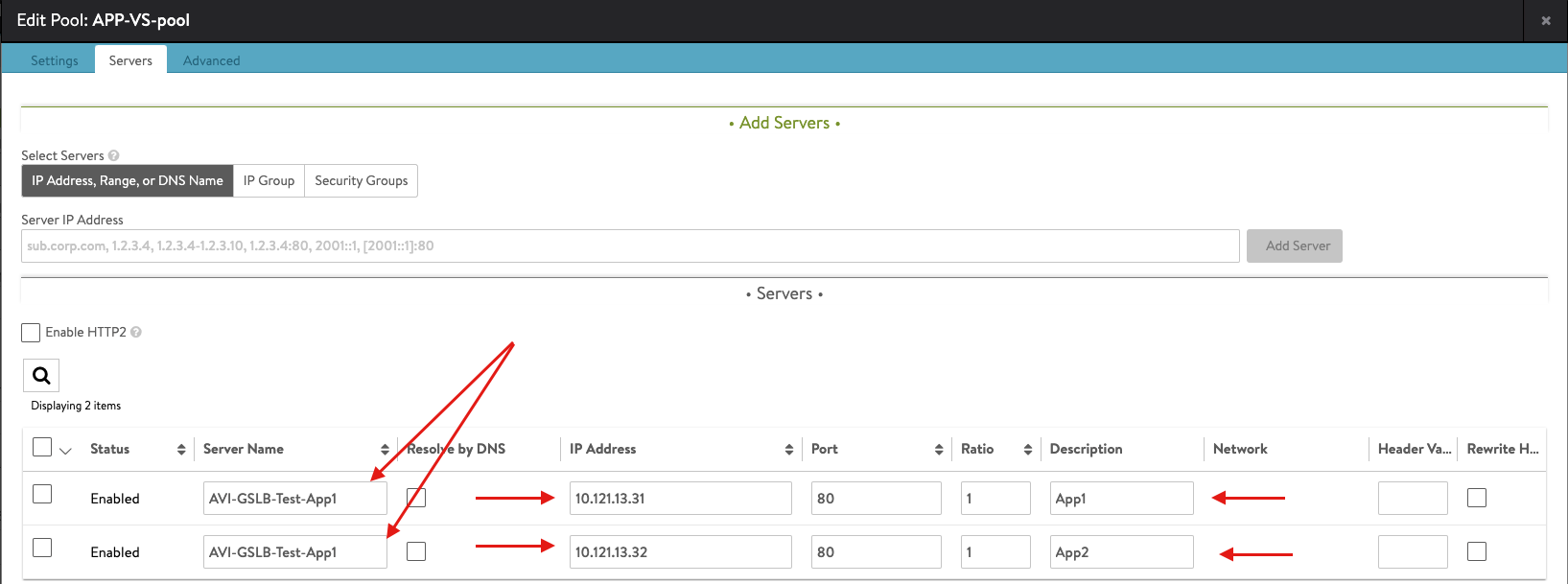
- Once you complete the Pool configuration, hit Save to complete the Virtual Service configuration
- Once you completed the configuration you should have something like the following:
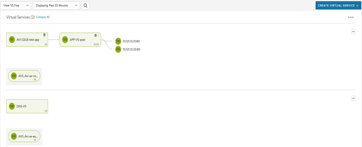
Configure Global Load Balancing for Azure VMware Solution
Once all the previous steps were completed successfully, you can move ahead with the GSLB configuration. First, we need to enable GSLB service as per below
I have selected the AVI Controller in AVS to be my leader GSLB controller, you can select only one leader controller in your setup.
let us first add your GSLB members to the GSLB leader (which is your AVS Controller)
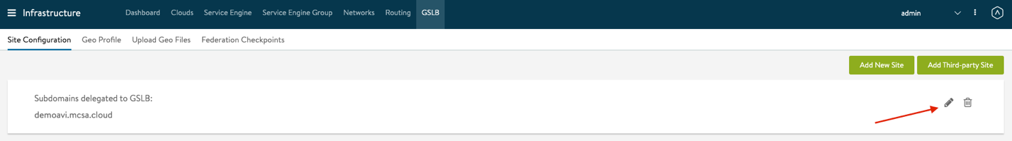
- From the Controller UI, navigate to Infrastructure > GSLB
- Select Create
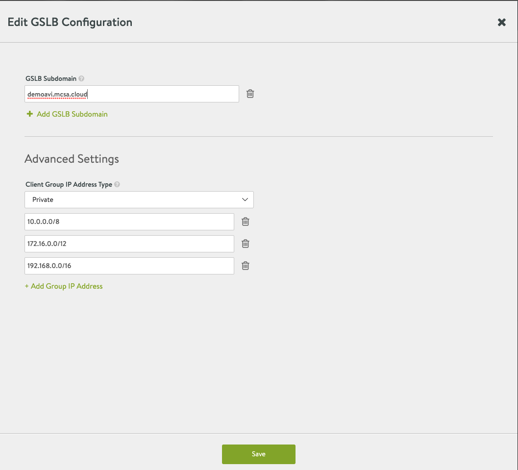
- Select Edit for your Subdomains delegated to GSLB and insert all the following information, once done hit save
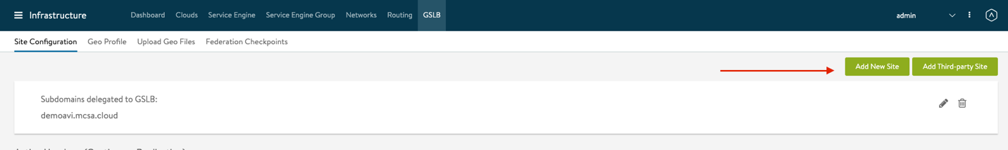
- Next select Add New Site to add the following sites to GSLB
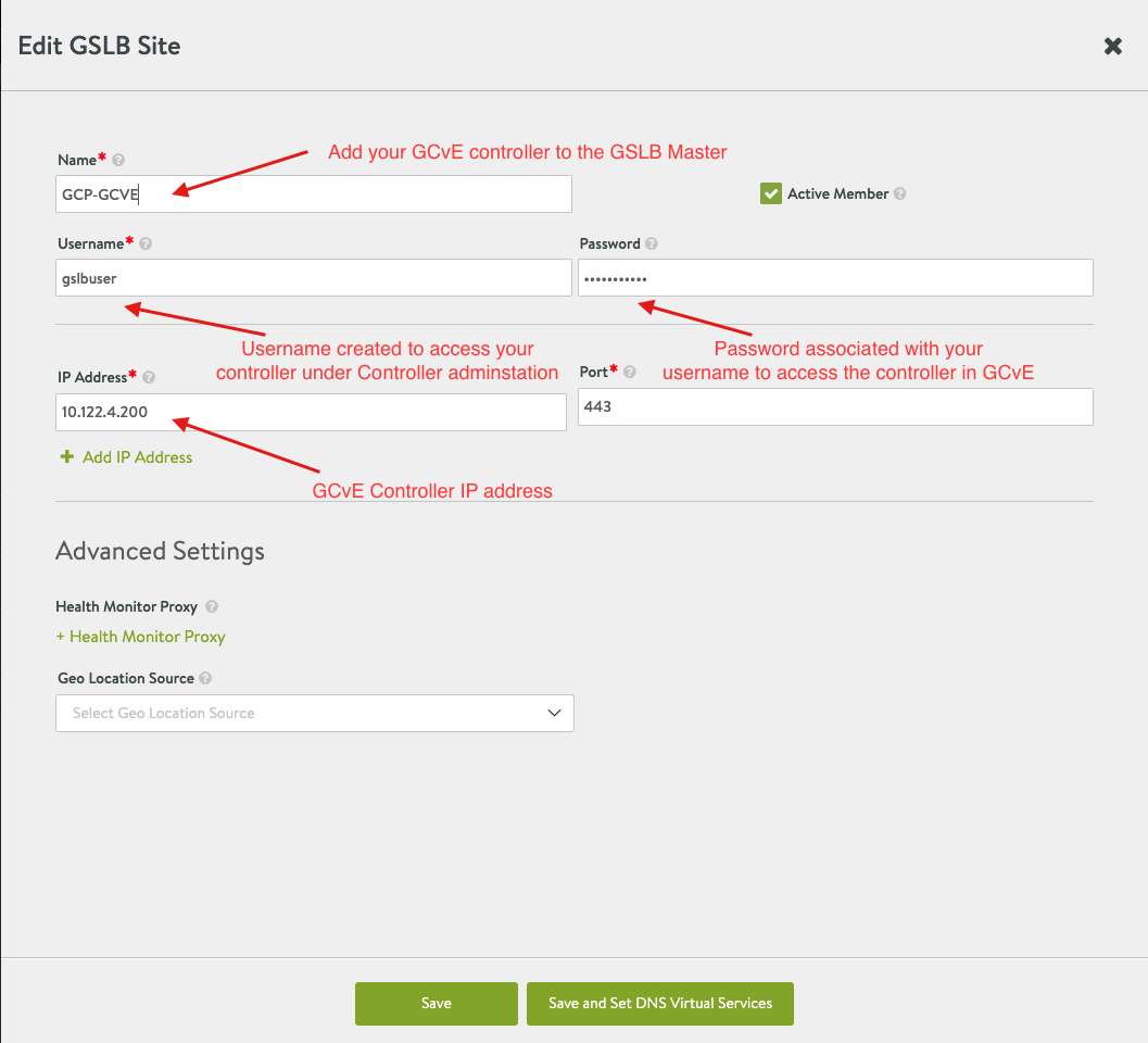
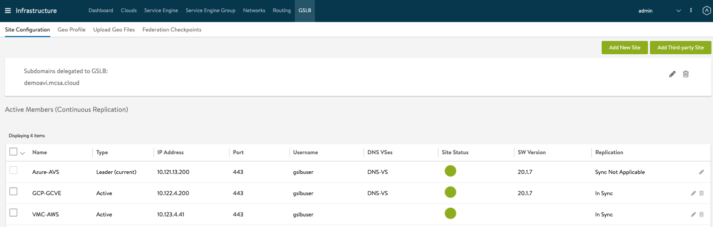
- Repeat the configurations in step 4 for all the other GSLB Sites. Once done, you should get a similar view, please note that Azure-AVS site is Leader and Sync Not applicable.
Next, You will apply your GSLB configuration for all the other SDDCs in the leader GSLB controller.
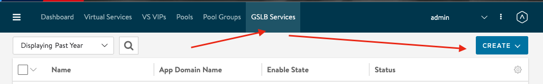
- From the Controller UI, navigate to Applications > GSLB Services
- Select Create
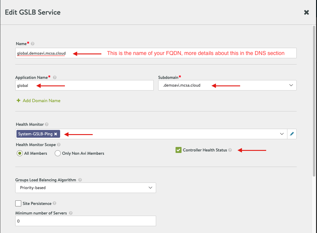
- Scroll down to GSLB Pools and select Add Pool
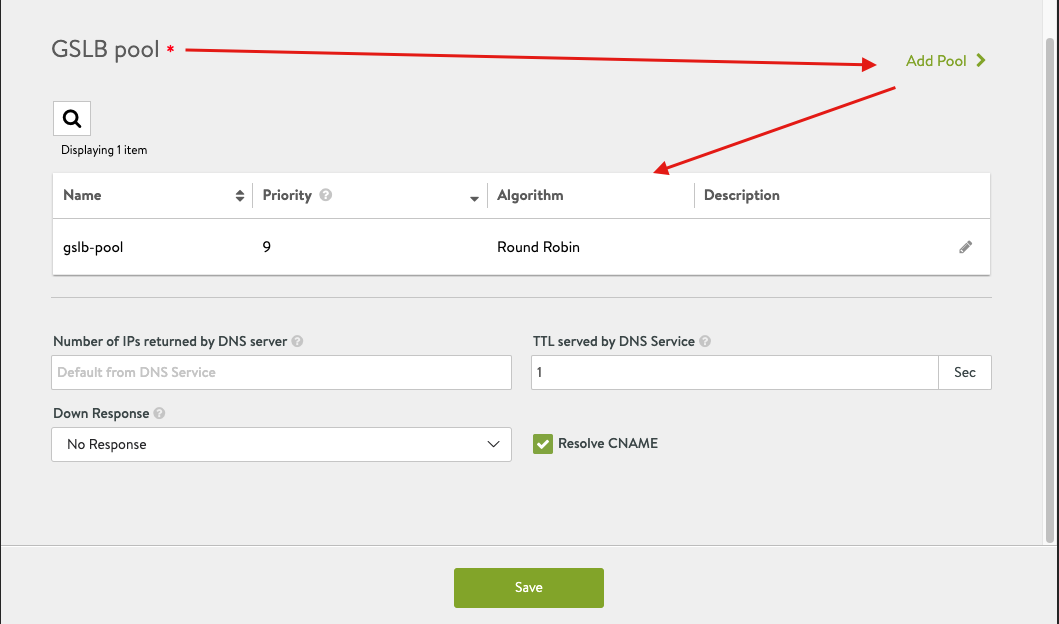
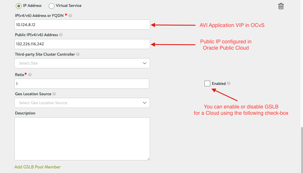
- Apply the following configuration, however, please note that you might need to revisit this section after completing your VMC, GCvE and OCvS sections to populate the required information.
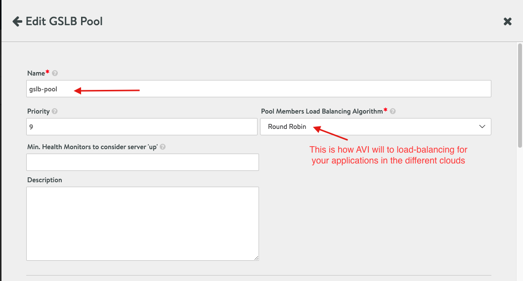
Please note, you have two options of adding Pool Member, I chose the IP Address, however, best practice is to add Pool members as Virtual service, my intention was to show you the IP addresses applied for each service.
- Once all the Cloud configuration has been applied you can select done.
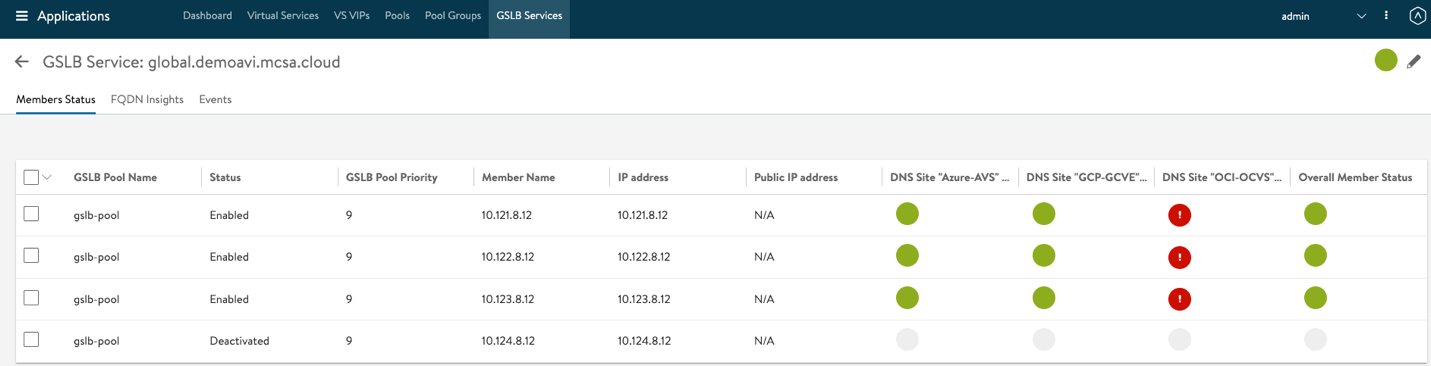
- Hit the GSLB Service link created after your last configuration, you should have a similar view to the following image, please note if any of your clouds are still initializing or running into some errors you should see Location un-available, in my case below my Oracle cloud is still initializing. Please do not move on unless all your clouds are green.
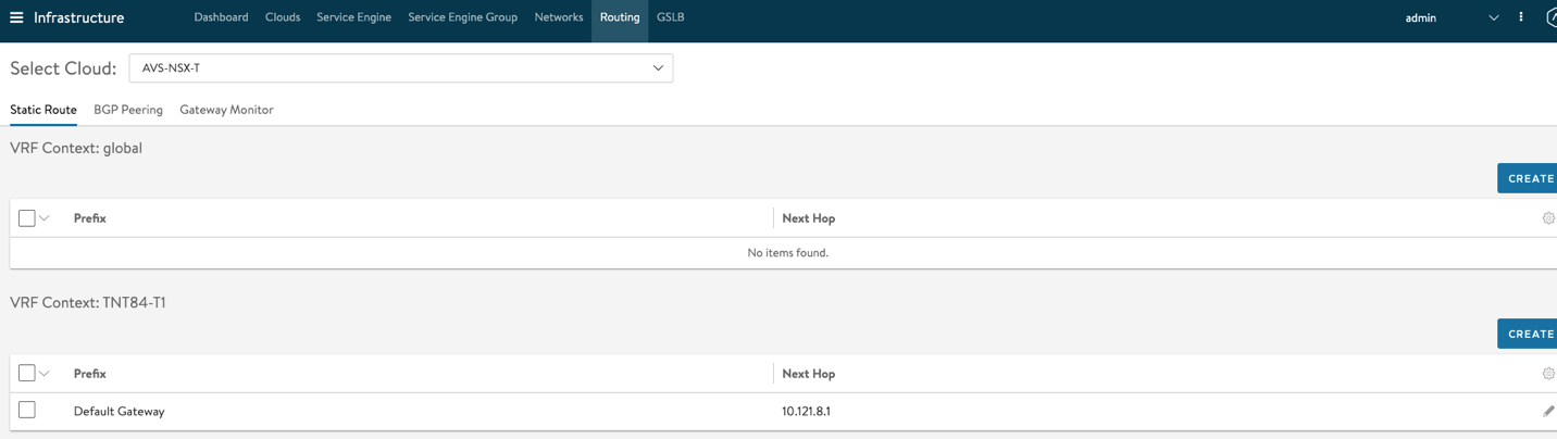
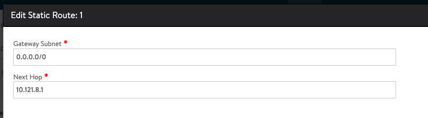
In some cases, you might need to configure Routing for your default Gateway in AVI, this configuration routes all your traffic to the AVI VIP.
To apply this configuration, navigate to Infrastructure > Routing. Make sure to Select your AVS-NSX-T Cloud. Under VRF Context, Select Create and configure 10.121.8.1 as the Next Hop for your default Gateway
Azure Configuration requirements for GSLB
One of the key AVI-GSLB requirements for multi-cloud VMware SDDC architecture, is to allow ingress and egress traffic from Azure to VMware SDDC and vice versa. But why is this a requirement? To understand this concept please read the following lines.
Think of VMware’s SDDC in Azure as a private isolated network that requires egress and ingress traffic management. Then, think of AVI GSLB as a network solution that allows users coming from external networks or even the internet and trying to access private workloads or applications in your isolated VMware SDDC in Azure.
Based on the previous statements and to make GSLB work we will need to allow external public traffic into the VMware private SDDC, this association requires some configuration on the public cloud side to allow traffic coming from the internet into Azure, then from Azure to VMware SDDC in the same for the opposite direction.
The association of public to private traffic is done using NAT’ing of public IPs to private IPs.
Please note, in this section I will only explain the configuration requirements for Azure, this configuration is not the same for all other public-cloud providers, for more information about each public cloud please see the dedicated section for each cloud.
** Azure does not allow public-IP configuration for Azure VMware Solution (AVS), for this reason I had to create a vWAN hub, on the vWAN hub I enabled a Firewall with a public-ip and couple Destination NAT rules.
This is the only available way today to allow public traffic into the private VMware SDDC. Please visit the future work section for more information. **
- Open your Azure portal, use the following link: portal.azure.com
- In search bar, search for Azure VMware Solution (assuming you already configured AVS)
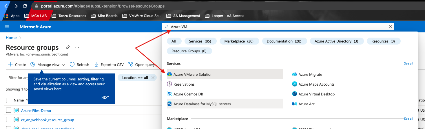
- Select your SDDC
- Under Manage, select Connectivity and select the Public IP tab
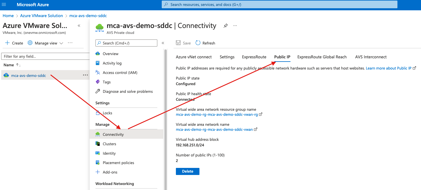
- If you are configuring a public-ip for the first time you will see the option of configuring a public-ip, in my case this configuration was already done.
- Click configure Public-ip, as mentioned previously, Azure will force you to configure a vWAN hub to all a public-ip for your SDDC. Starting April/May 2022, Azure will allow you to configure a public-ip without using vWAN hub, for more information check the future section on this document.
- Go through the vWAN hub configuration, for more information about vWAN hub configuration please use the following link: https://docs.microsoft.com/en-us/azure/virtual-wan/virtual-wan-about
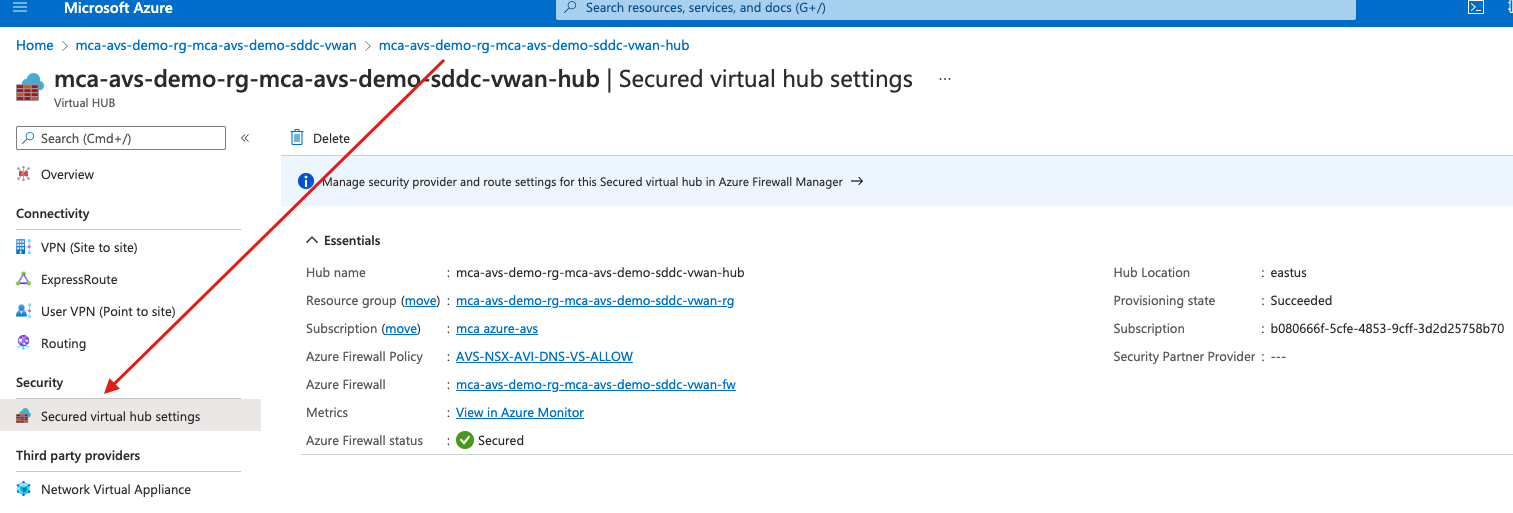
- Once your vWAN hub is fully configured, you can now navigate to your hub to configure a vWAN Firewall, please note you will need this firewall to control ingress and egress traffic and to create DNAT (Destination NAT) rules to map your Public to private IP address.
- In your vWAN hub, navigate to Security and select Secured virtual hub settings.
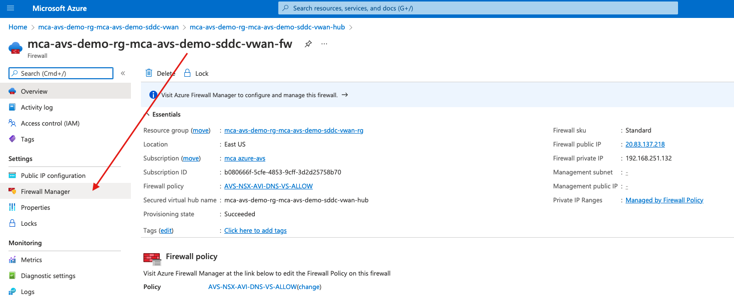
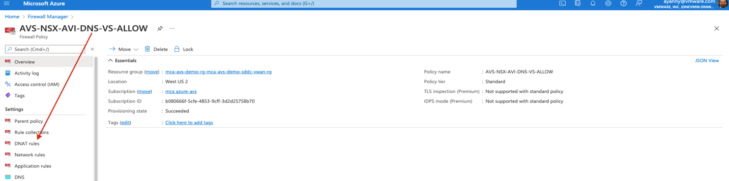
- Navigate to vWAN FW on the right side, if you don’t have the same view, use the search bar to find your vWAN FW, from there navigate to Firewall Manager.
- Under Firewall manager navigate to Azure Firewall policies.
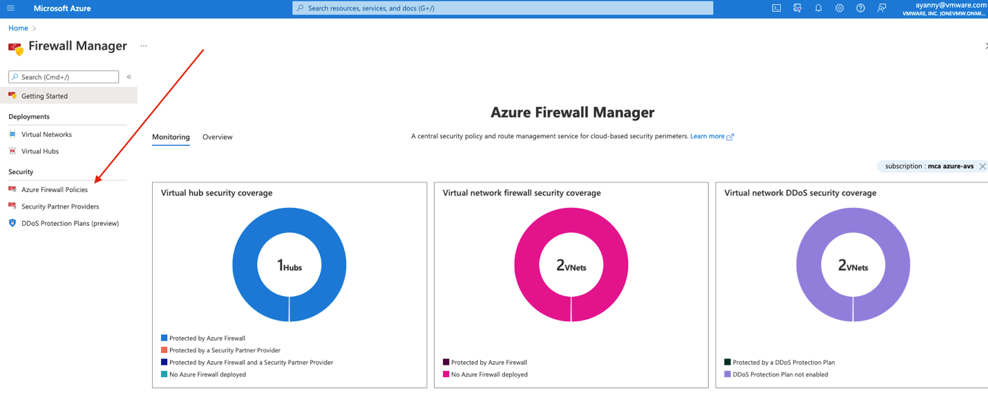
- Select Create Azure Firewall Policy. Make sure to create the following DNAT rules to manage egress/ingress mapping once you create the Firewall policy.
- Apply the following DNAT configuration, make sure to apply the proper IPs as per your configurations.
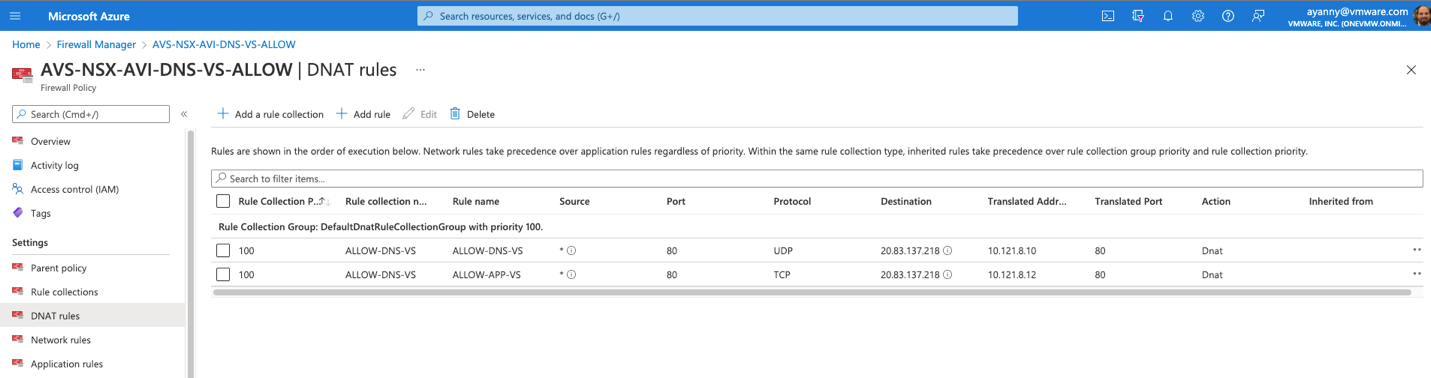
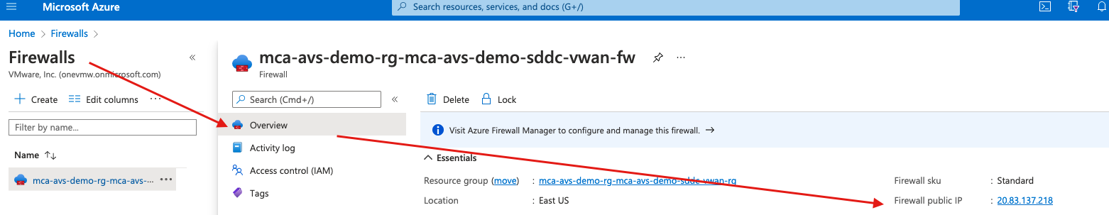
Please note, you can find the public-IP of your Firewall if you navigate to firewall and select Overview
- Finally navigate to your policy and associate the policy with your hub.
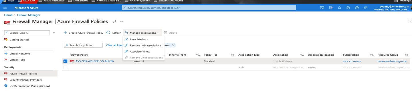
Assuming your Global DNS configuration is fully completed, if you navigate to http://global.demoavi.mcsa.cloud/ you should be able to reach your AVS private workload
Deploy AVI-GSLB on Google Cloud VMware Solution
To deploy AVI-GSLB on Google Cloud VMware Solution you will need to follow similar steps discussed on the following location on this document here
Configure NSX-T networking as per instructions show in here
Once AVI is installed, you can configure AVI GSLB, for more information follow steps discuss in the following location on this document here
AVI general Installation and initial configuration guide here or follow the following link: https://avinetworks.com/docs/21.1/avi-deployment-guide-for-google-cloud-platform-gcp/
Note, although GSLB configuration is very similar on most of the SDDCs, you will notice that GSLB configuration is only allowed at the Azure VMware Solution because it is the GSLB leader.
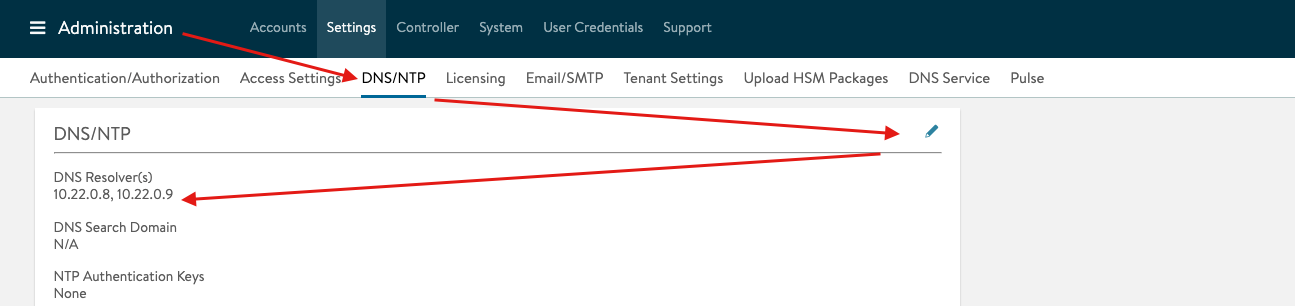
DNS Configuration Tip:
In some cases, you will need to configure DNS resolvers for your AVI controller. The required DNS resolvers are the Google Cloud VMware Solution DNS IPs. To apply the following configuration, you need to access your AVI controller and navigate to Administration > DNS/NTP, then add the GCvE private DNS resolvers:
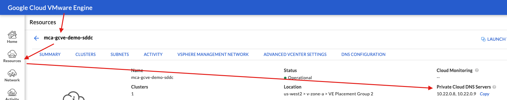
You can locate the GCvE DNS resolvers by accessing your GCvE Solution in GCP, then navigate to Resources > Summary
Google Configuration requirements for GSLB
As previously discussed, public cloud configurations for the VMware SDDCs are different for each cloud. That being said, we will discuss the required configuration to enable AVI GSLB for Google Cloud.
Assuming you already have Google Cloud VMware Solution already deployed
- Navigate to your Google Cloud platform and search for Google Cloud VMware Solution in the search bar.
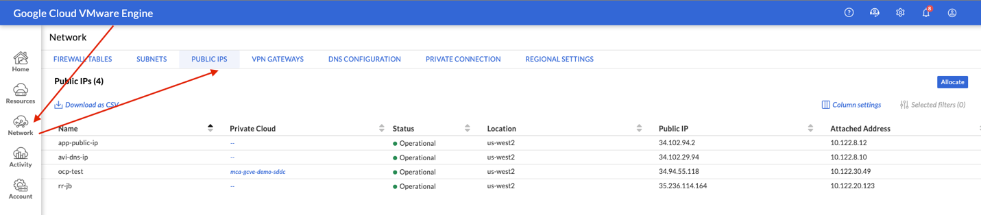
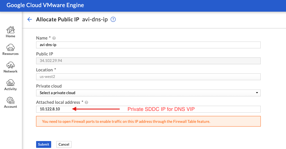
- Navigate to Networks on the left side Menu and select Public IP, you need to create two public-ips and map the public-ips to two private-ips. One public-ip is required for the application VIP and the other public-ip is required for the DNS VIP.
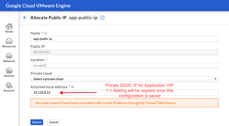
- Select Allocate and apply the following configuration. By default, GCP will allocate a public IP for you, you need to add a Name and Attach a local address. Google does 1:1 NATing by default once you apply this configuration. Once you apply the below configuration hit submit
- Select Allocation again and configure a DNS Public-ip mapping, once you apply the below configuration hit submit
- Next, we will need to allow traffic to flow between GCP and GCvE, this is the traffic coming from internet or external networks to our SDDC. To allow this, you need to navigate to Firewall Tables > Create New Firewall Table and allow traffic for the public/private IPs you created in the previous steps. Please make sure you allow traffic for ports 443 and port 80 as per below.
Assuming your DNS configuration is fully configured, if you navigate to your application address, you should be able to reach your AVS private workload. In my case (http://global.demoavi.mcsa.cloud/)
Architecture Note: GCP creates a small internet Gateway when you deploy Google Cloud VMware Solution. This Internet Gateway is what I used to control egress and ingress internet traffic to the VMware SDDC. It is not recommended to use this internet Gateway for your traffic, but rather deploy a GCP internet Gateway and use it for your SDDC ingress/egress traffic. For more information, please review the future work section.
Deploy AVI-GSLB on VMware Cloud on AWS
Deploying AVI on VMC on AWS is a slightly different process that the one explained for Azure (here). I recommend you visit the following link and follow the process to download, install and configure AVI: https://avinetworks.com/docs/20.1/avi-vantage-integration-with-vmware-cloud-on-aws/
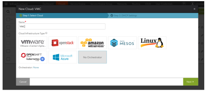
You will find that the AVI Configuration process is straightforward, however, one thing to keep in mind is that you will need to choose the No Orchestrator Cloud for your VMC deployment.
VMware Cloud on AWS Networking and Security Configuration for AVI
After installing AVI in your VMC environment, you will need to configure networking and security in VMC to ensure that AVI can communicate with applications in your SDDC and the public networks and/or Internet.
Here are all the required steps you need on VMC on AWS.
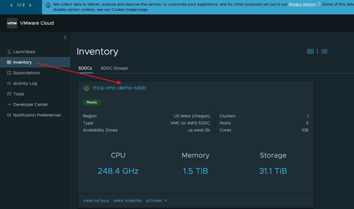
- Navigate to your SDDC in your vmc.vmware.com portal
- Select the Networking & Security tab then select Public IPs. Select Request New IP and add two IPs, one for your DNS-VS and a second one for the Application VS
- Navigate to Networking & Security > Segments. We will need to configure NSX Segments for AVI. Wv-usw2-avi-data (10.123.8.1/24), wv-usw2-shared-internal (10.123.4.1/24) and wv-s-usw-avi-mgmt (10.123.254.1/29). Configuring segments is as easy as selecting Add Segment.
- Next, we will need to configure Security to manage our egress and ingress traffic for our SDDC. Navigate to Network & Security > Security > Gateway Firewall. Select Add Rule and create the following rules to allow inbound and outbound traffic.
![]()
![]()

Note, it is recommended to configure Groups under Inventory for ease of management.
- Finally, we need to configure NAT, to map the external IPs to the internal IPs. Navigate to Networking & Security > Network > NAT > ADD NAT RULE and add the following NAT Rules.
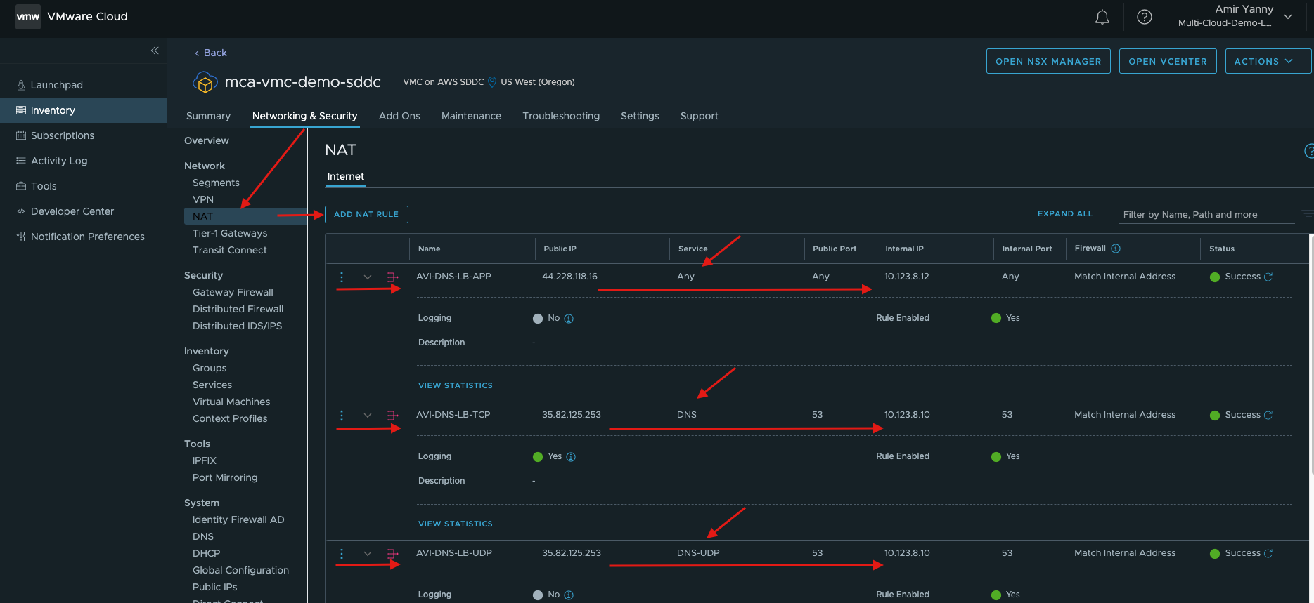
For more information on AVI virtual services and pool configurations, please follow instructions in here.
Assuming your DNS configuration is fully configured, if you navigate to your application address, you should be able to reach your VMC private workload. In my case (http://global.demoavi.mcsa.cloud/)
Deploy AVI-GSLB on Oracle Cloud VMware Solution
As previously discussed, public cloud configurations for the VMware SDDCs are different for each cloud. That being said, we will discuss the required configuration to enable AVI GSLB for Oracle Cloud Infrastructure.
Assuming you already have OCVS (Oracle Cloud VMware Solution) already deployed
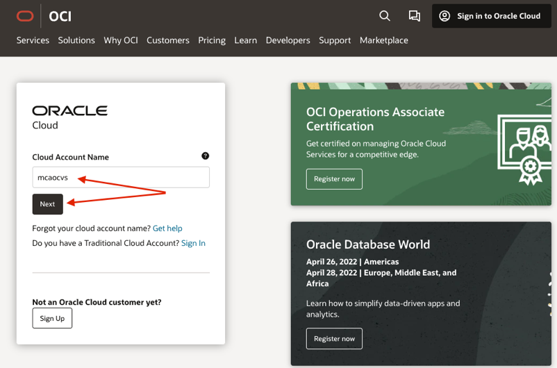
- Navigate to your OCI and access your Cloud Account Name (mcaocvs) and hit next
- Using the Hamburger menu on the top left navigate to hybrid
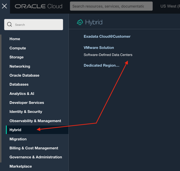
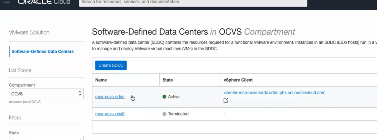
- Access your SDDC
![]()
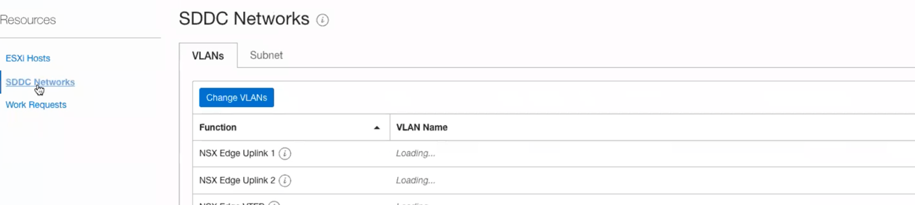
- Scroll down and click on the networks tab (SDDC Networks)
![]()
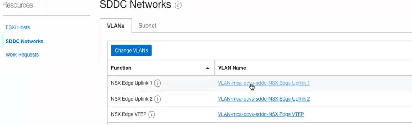
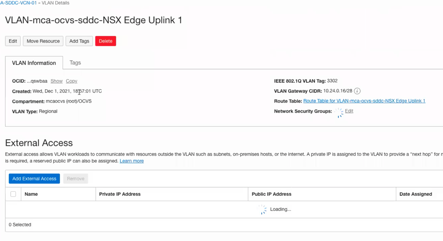
- Now, click on NSX Edge Uplink 1 (By default you should have more than 1 uplink automatically deployed for you by default)
![]()
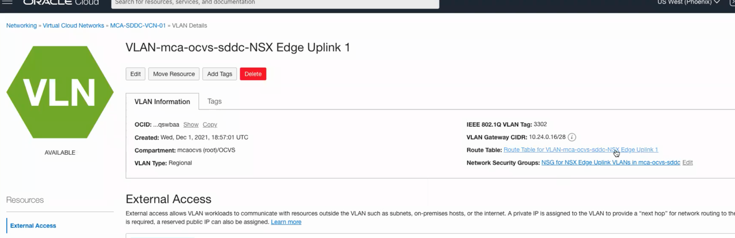
- Now, navigate to the route table on the right-hand side, we need to set a route a default route to send all traffic from our SDDC to hit the Internet Gateway.
![]()
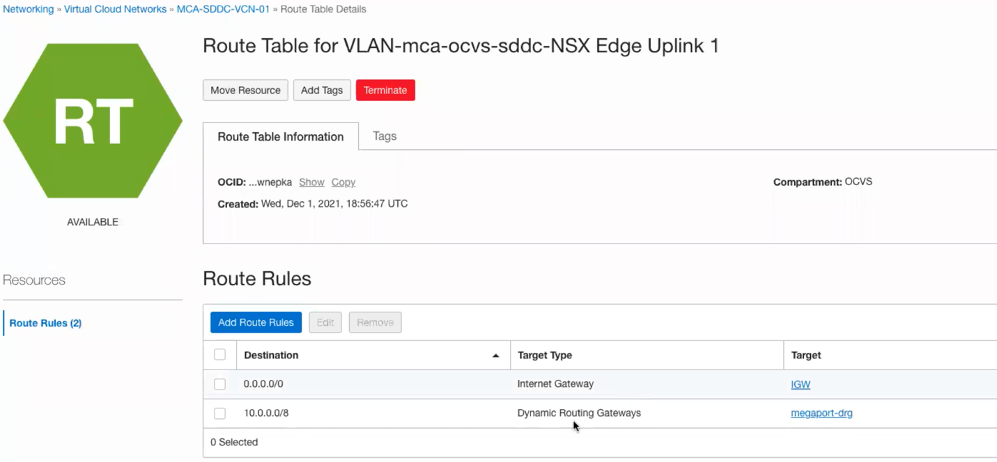
- Navigate to Add Route Rules and add a quad zero (0.0.0.0/0) with a next hop as IGW as per below
![]()
![]()
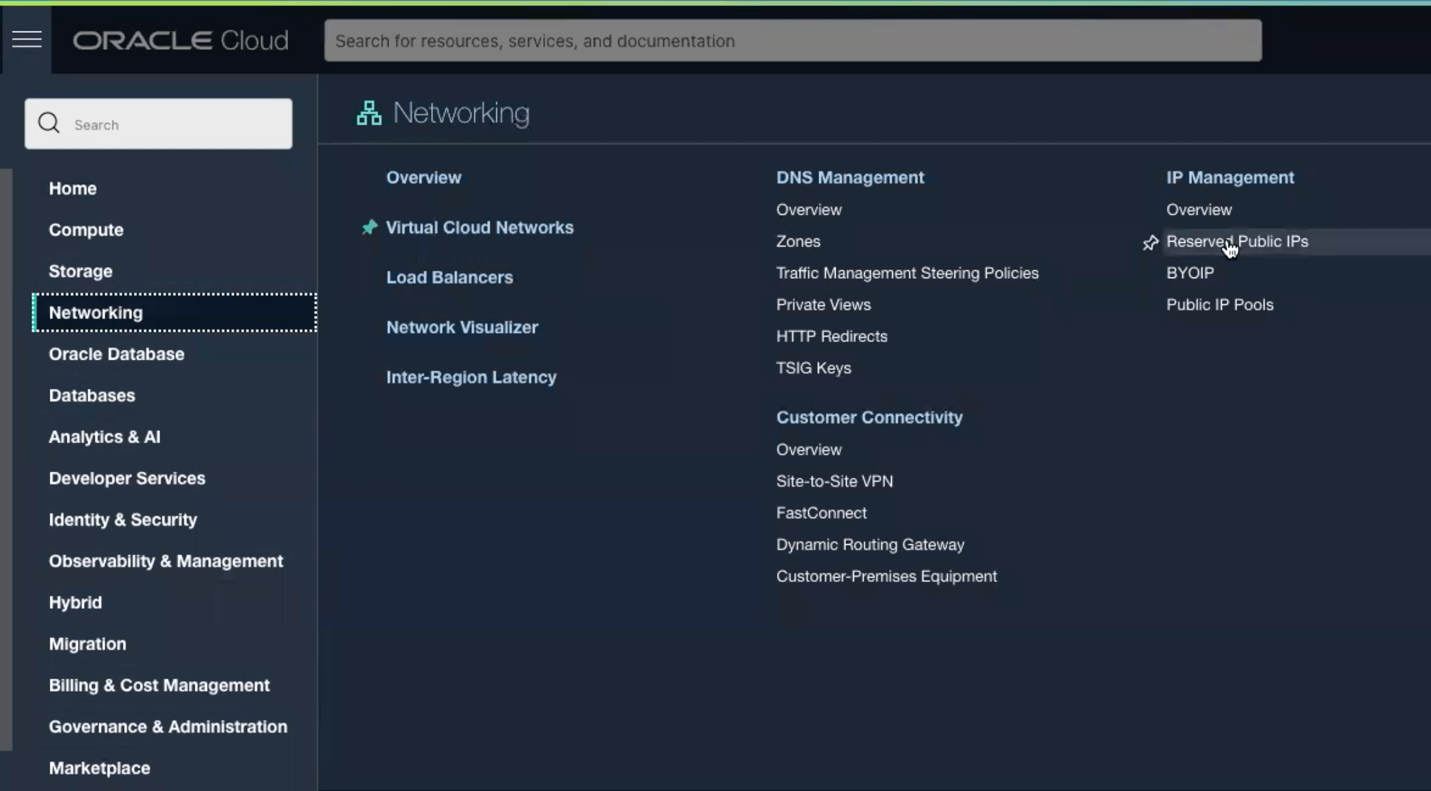
- Now click again on the hamburger menu, go to networking and click on Reserved Public IP’s on the right hand side.
![]()
![]()
- Click on Reserve Public IP address
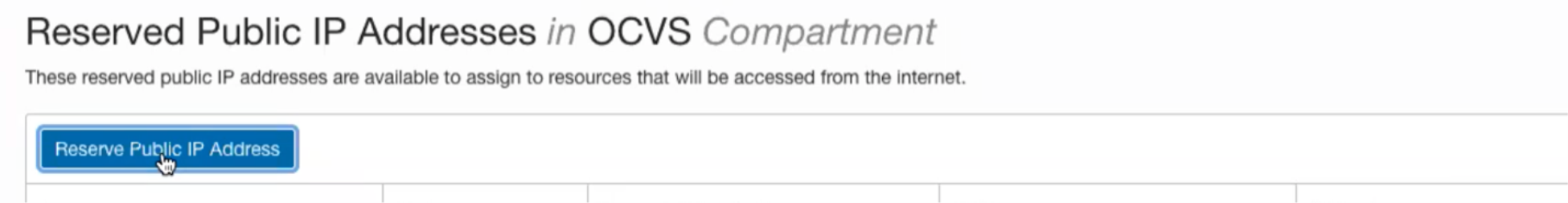
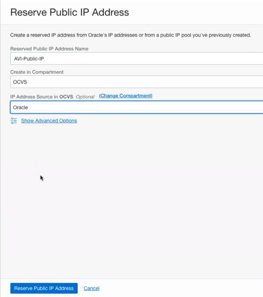
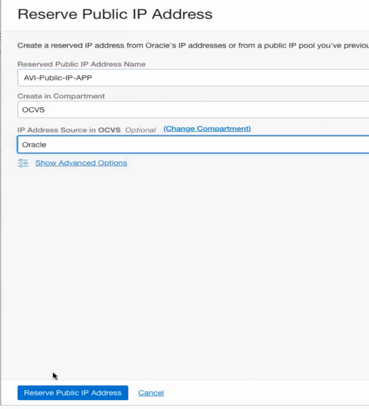
- Reserve two Public facing IP address, one for your Application Virtual Service and one for your DNS Virtual Service.
| | |
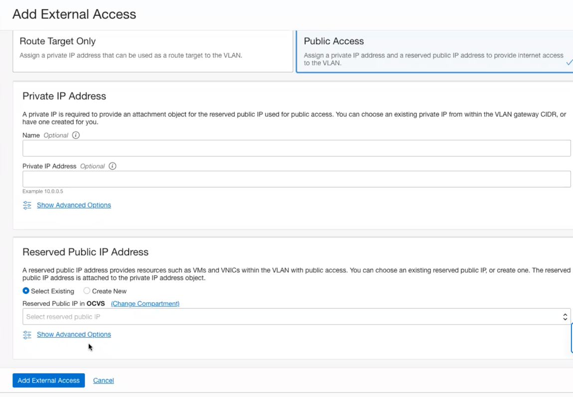
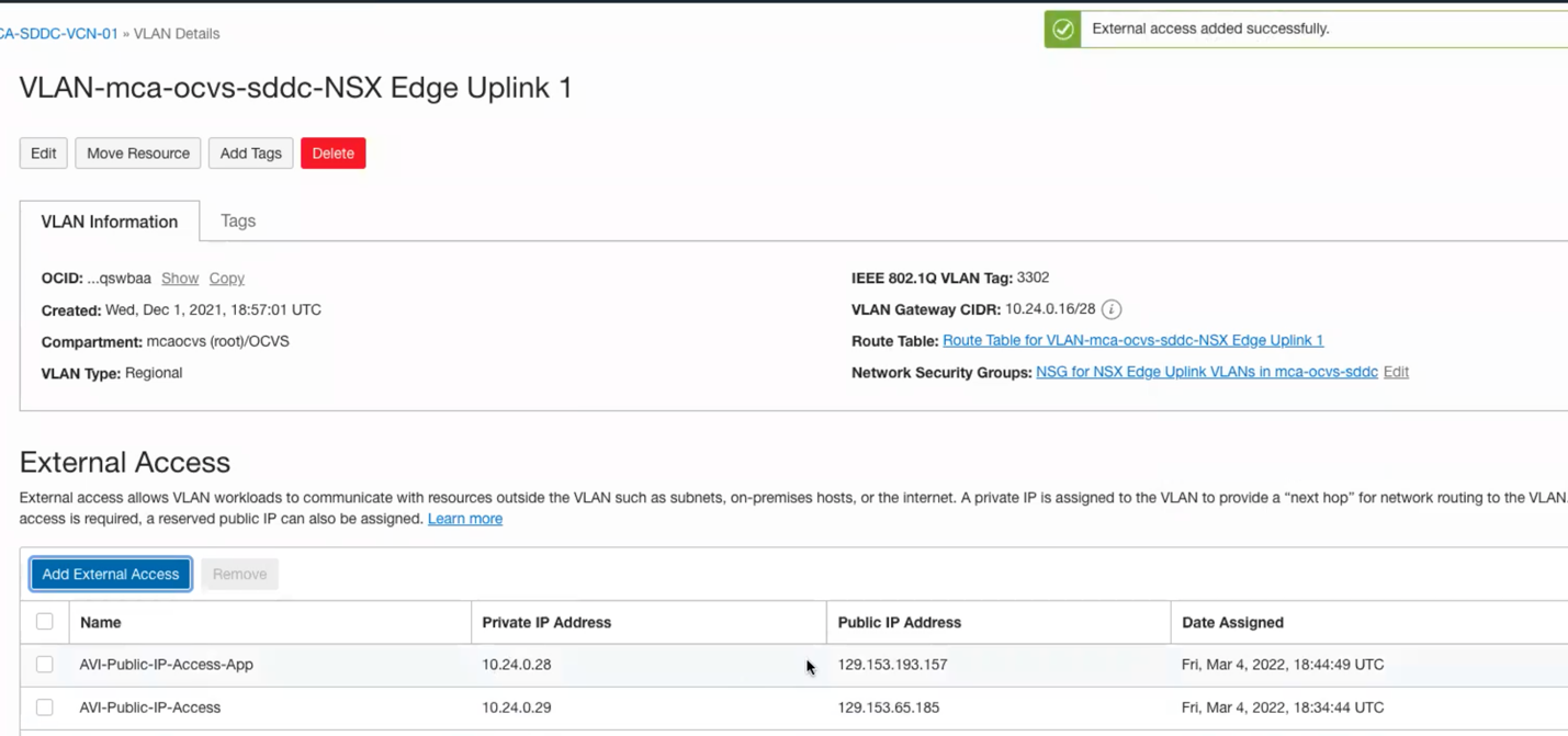
- Now repeat steps 2, 3, 4, 5, then click on Add External Access
![]()
- Choose Public Access then click Reserve Public IP, and choose the Public IP created in the previous steps.
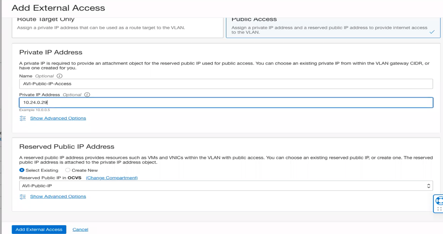
![]()

- In the Private IP Address section, give your private IP a name and then choose a free IP in your VLAN Gateway CIDR block (check the screen shot in step 11, this is where you see your Gateway CIDR block), in my case I will choose 10.24.0.29 for the DNS-VS, then Click Add External Access.
- Repeat the previous step and add external access for the application virtual service, the will map the internal IP 10.24.0.28 to the public ip assigned for the application.
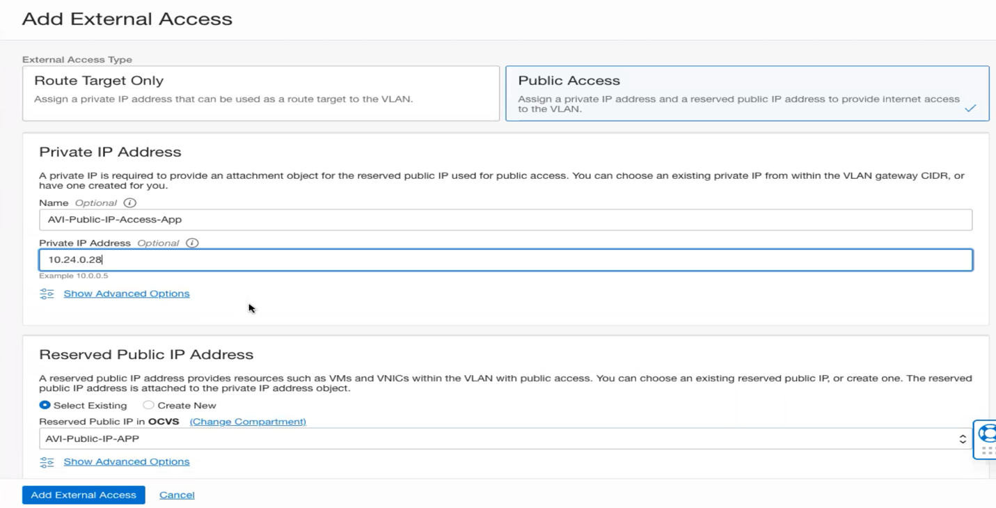
- You should see a similar view to the below snap-shot
- Now go ahead and open the SDDC manager for this SDDC. Once you open NSX, go to the networking tab and click on NAT then Add NAT Rule.
![]()
![]()
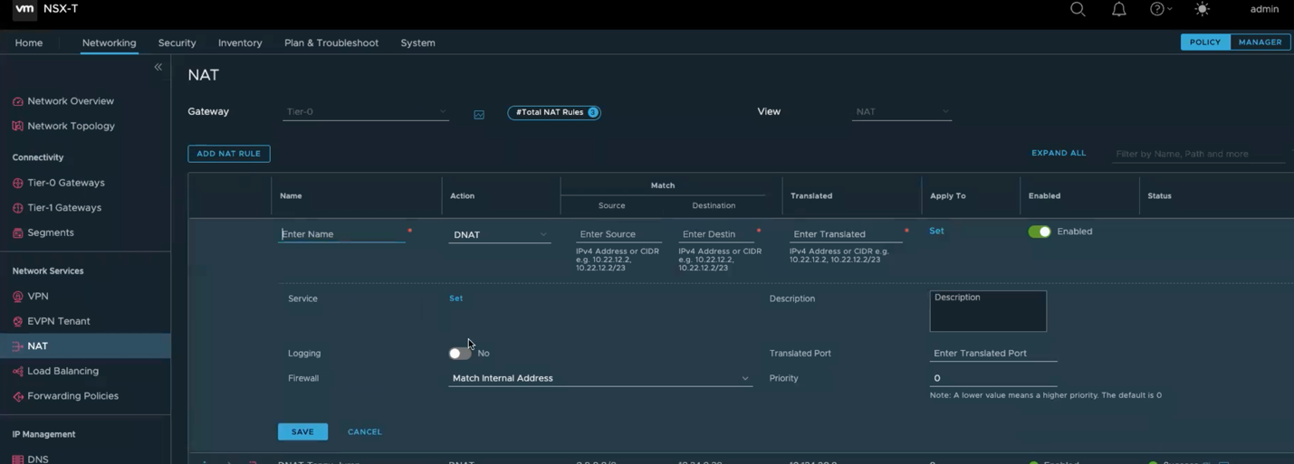
- Apply the following configuration to create a DNAT Rule to NAT traffic for DNS Virtual Service:
- Name: AVI-DNAT-DNS
- Source: leave it blank (Represents Any)
- Destination: 10.24.0.29
- Translated: 10.124.8.10 (AVI IP address of the DNS-Virtual Service)
- Apply to: Hit Set and choose NSX-Edge-Uplink-1
- Hit Save
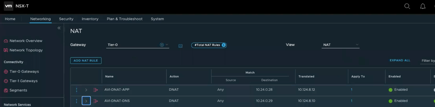
- Apply the following configuration to create a DNAT Rule to NAT traffic for Application Virtual Service:
- Name: AVI-DNAT-App
- Source: leave it blank (Represents Any)
- Destination: 10.24.0.28
- Translated: 10.124.8.12 (AVI IP address of the Application-Virtual Service)
- Apply to: Hit Set and choose NSX-Edge-Uplink-1
- Hit Save
- Once you finish the previous two steps you should get a similar view to the following image
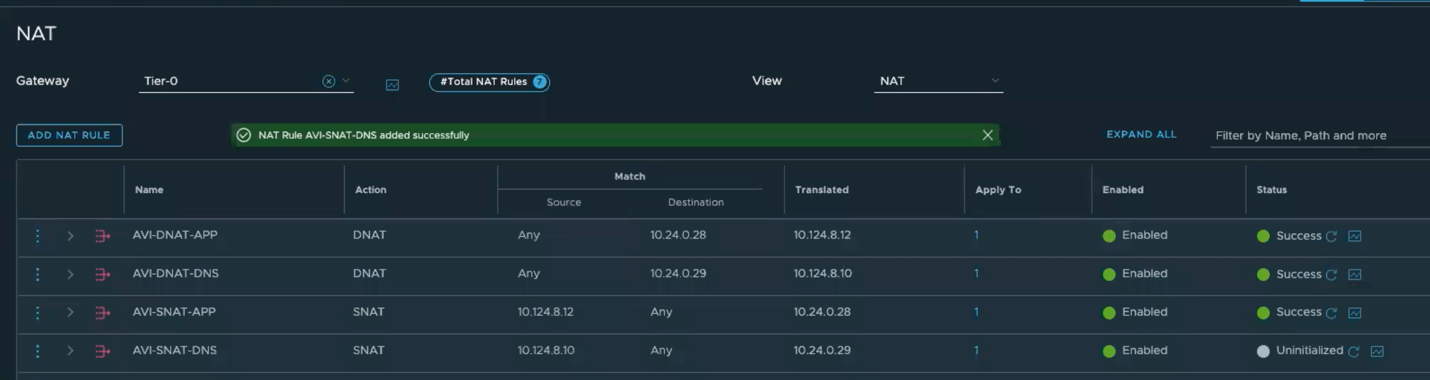
- Now we need to create couple outgoing Source NAT rules
- Rule1:
- Name: AVI-SNAT-DNS
- Source: 10.124.8.10
- Destination: Any
- Translated: 10.24.0.29
- Apply to: Hit Set and choose NSX-Edge-Uplink-1
- Hit Save
- Rule2:
- Name: AVI-SNAT-APP
- Source: 10.124.8.12
- Destination: Any
- Translated: 10.24.0.28
- Apply to: Hit Set and choose NSX-Edge-Uplink-1
- Hit Save
- Once you completed the previous step you see a similar view
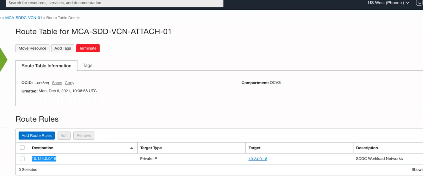
Finally, there are couple more things we need to make sure are in place. Go to the hamburger menu, click on networking and Click on Dynamic Routing Gateway, click on your SDDC, then click on the attachment, then click on the VCN Route Table as per below image

![]()
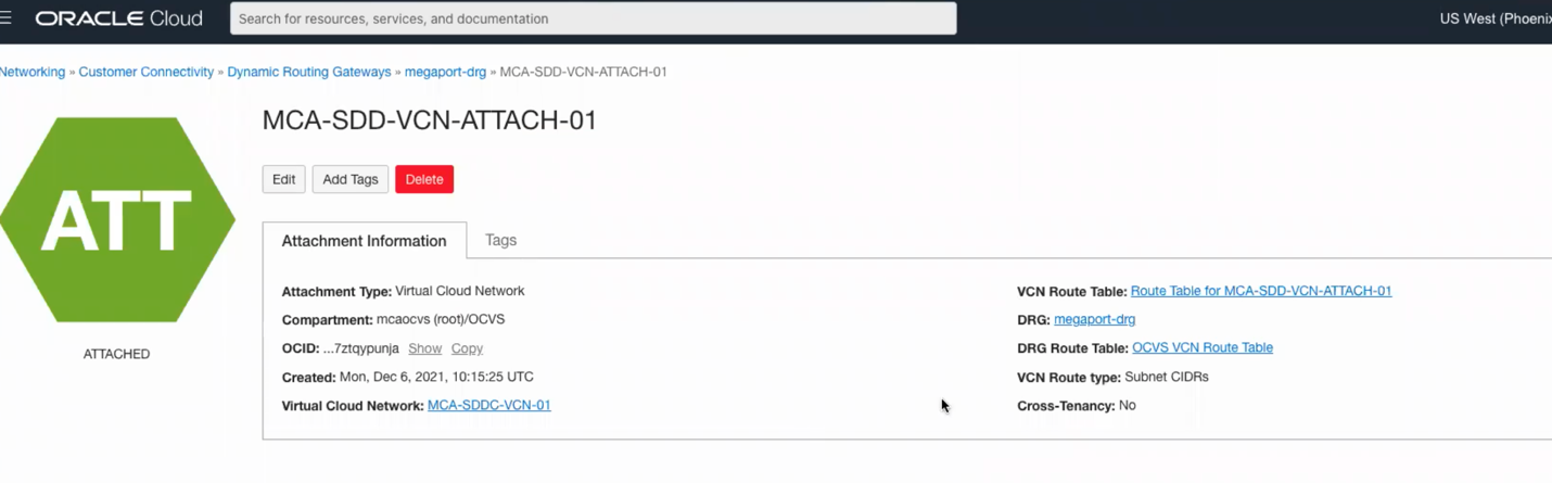
Make sure you SDDC range (10.124.0.0/16 in my case) is forwarded to right target
This completes all the required configuration on the OCI side, the next steps is to deploy AVI in OCVS, this is a vSphere deployment identical to the deployment we did early in this document found here. You can also follow the AVI configuration found here.
Global DNS Configuration using Route53
One of the real important things when it comes to AVI GSLB when you are using Route53 is domain delegation.
If you don’t have a domain name setup in Route53, go the following link and follow the instructions: https://www.bogotobogo.com/DevOps/AWS/aws-Route53-DNS-Domain-Name-Server-Setup.php
In my case, I have a domain name already configured which I am going to use “mcsa.cloud”. Next, I will configure a sub-domain for my AVI GSLB. More details in the table below.
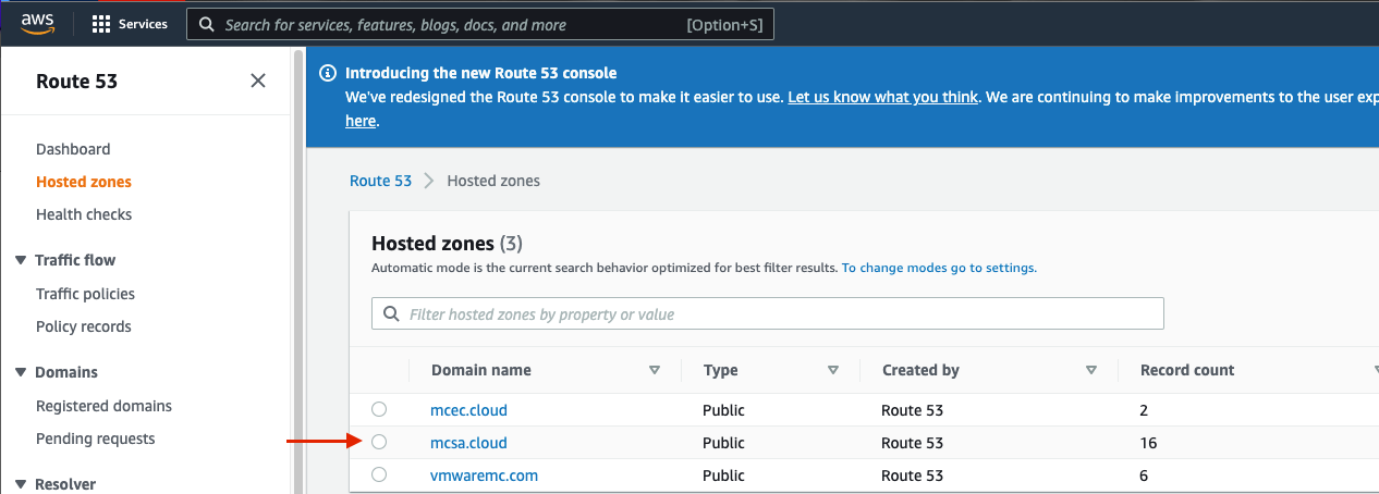
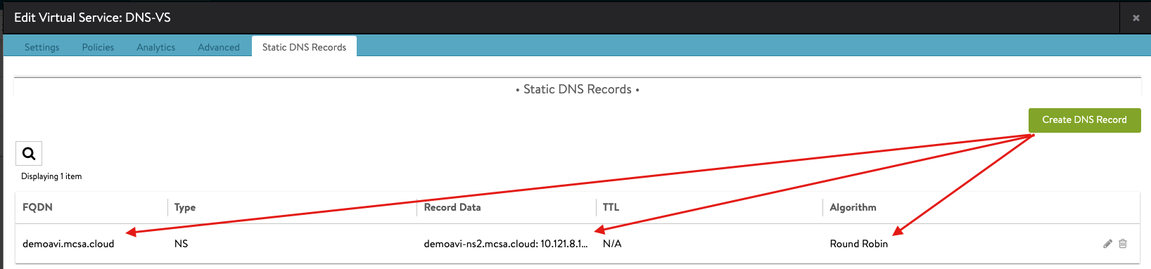
The next step is to create A and NS records for your AVI GSLB, you can apply similar configuration to what I create. Simply navigate to hosted zones > your domain > Create Record.
Then I have my NS record effectively saying, anything that has “demoavi.mcsa.cloud” in it, go ahead and send them to the associated name servers in the table below.
Once you apply this configuration, and you query the “demoavi.mcsa.cloud”, Route53 will route traffic to these AVI authoritative servers based on your AVI GSLB configured algorithm (In my case Round Robin, for more information visit the configuration in here and go to step 4)
| Record Name | Type | Routing | Value/Route Traffic | Notes |
| demoavi-ns1.mcsa.cloud | A | Simple | 20.83.137.218 | DNS-VS Public IP |
| demoavi-ns2.mcsa.cloud | A | Simple | 34.102.29.94 | DNS-VS Public IP |
| demoavi-ns3.mcsa.cloud | A | Simple | 35.82.125.235 | DNS-VS Public IP |
| demoavi-ns4.mcsa.cloud | A | Simple | 158.101.45.54 | DNS-VS Public IP |
| demoavi.mcsa.cloud | NS | Simple | demoavi-ns4.mcsa.cloud demoavi-ns3.mcsa.cloud demoavi-ns2.mcsa.cloud demoavi-ns1.mcsa.cloud |
|
Note, The IPs in the table are the DNS-VS IPs that you configured for each public cloud provider, for more information check the following:
VMware AVI-GSLB multi-cloud Support Statement
VMware AVI supports deployment across private data centers and multiple public clouds for true hybridity.
Restrictions may apply depending on the versions running and licensing for VMware AVI and VMware infrastructure sites.
Future Work
Field AVI Demo Access
The Multi-Cloud team is working on a strategy to provide lab access to the field teams to demo AVI GSLB for multi-cloud SDDC deployments. For more information on this please reach out to @Amir Yanny or @John Marrone from the Multi-cloud architecture team
AVS Architecture future work
Public-IP for AVS
At the time of writing these lines, Azure has not yet developed the Public-IP feature for AVS. The only way to enable Public-IP for AVS is to configure vWAN as discussed elsewhere on this document.
vWAN hub + Azure Firewall adds additional costs that must be taken in consideration.
Azure will release Public-IP for AVS on April/May 2022, once this feature is added I will update the document to include this option.
GCVE Architecture future work
Google Cloud VMware Solution – Internet Gateway
When a GCvE is deployed in Google, a smaller version of an Internet Gateway is deployed for GCvE, this internet Gateway handles internet traffic for your GCvE deployment.
It is important to know that this Internet Gateway is not capable of handling large amount of traffic and might not be a good design consideration for production traffic.
It is recommended to route traffic from your GCvE Solution to a Google VPC Internet Gateway that is capable of expanding based on customer traffic demands.
I will discuss how to leverage a Google VPC Internet Gateway in later versions of this document.
OCVS Architecture
It is recommended to read the following two blog posts for more information about internet accessibility for OCVS.
https://notthe.blog/2021/11/ocvs-internet-access-1/
https://notthe.blog/2022/01/ocvs-internet-access-2/
Changelog
The following updates were made to this guide:
| Date | Description of Changes |
| 2022/05/18 |
|
Author and Contributors
- Amir Yanny, Sr. Multi-Cloud Solutions Architect, VMware