
Designlet: VMware Cloud on AWS Static Routing on Multiple CGWs (T1s)
Introduction
This document will provide recommendations and guidance on using static routes on multiple Compute Gateways (CGWs) also referred to as Tier-1 gateways (T1s) in VMware Cloud on AWS. The ability for customers to create additional T1s was added to VMC on AWS in the 1.18 release. These additional T1s can be used for a number of designs including application segmentation, multi-tenancy and overlapping IP addresses. The ability to configure static routes on the T1s was introduced and opens additional network topology options. The static routing feature will be the focus on this document.
Summary and Considerations
| Expected Use Cases |
North/South perimeter/zone firewall Load Balancer configured for in-line mode VPN or remote access endpoint |
| Inappropriate Use Cases |
In-line tap (packet inspection) Customer managed appliance (CMA) as the default gateway for workloads |
| General Consideration |
VMware Cloud on AWS is a managed service and as part of being able to deliver on the SLA, visibility into the complete network path is important. Introducing a customer managed appliance (CMA) into the network path creates a gap into VMware support’s visibility. Customers using this capability take the ownership of the correct operation of the CMA and potential disruption in the network path caused by incorrect operation of the CMA. Guidelines for deployments
With any CMA deployment, the customer is responsible for ensuring their appliance will support the VMC SDDC version after any upgrades. VMware will not do any compatibility testing for CMAs. |
| Performance Considerations |
When a customer managed appliance (CMA) is part of the network path, there are multiple considerations to plan for.
|
| Cost Implications | Potential need for higher performance VMC hosts to accommodate additional traffic recirculation. Additionally, the CMA may require licenses to meet throughput requirements. |
|
Documentation Reference |
Understanding VMware Cloud on AWS Network Performance |
| Last Updated | April 2022 |
Planning
When preparing to deploy a customer managed appliance (CMA) in a VMC on AWS SDDC, there are a number of points to take into account to ensure a successful deployment. The first will be the topology selection, specifically considering where the CMA will integrate into the network.
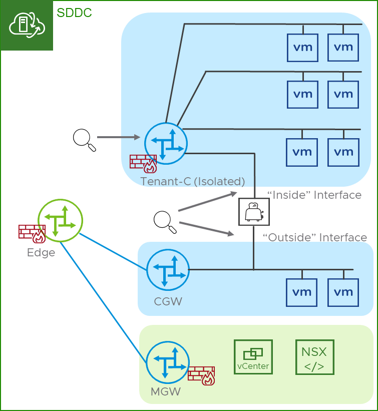
- CMA in a transit network configuration – this is the recommended model because of the ability to scale the number of segments behind the T1. An additional benefit is that this model, where the T1 is the default gateway on the isolated segments, allows VMware support services to have some visibility into the network. Since traffic must flow through the T1 to reach the CMA and egress the Isolated T1, this provides a point of traffic collection if needed during troubleshooting.
- CMA as the default gateway – this is not recommended because of the limited scale of segments behind the T1. Virtual machine guests can support 9 vNICs. With one vNIC being used to connect to the routed T1, this leaves 8 vNICs for the CMA to connect to the segments which limits the overall scale for each Isolated T1. In addition to limited scale, a topology where the T1 is not the default gateway provides VMware support services limited visibility into the network during troubleshooting activities. One more consideration is that the ability to use native NSX DHCP services are excluded when the CMA is the default gateway. NSX DHCP services use the IP address assigned to the T1 on the segment as the default gateway in the DHCP response. This is not configurable and as such would prevent the CMA from being the default gateway.
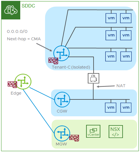
Figure 1 - CMA in a transit network configuration
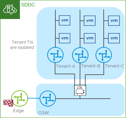
Figure 2 - CMA in a transit network configuration - alternate
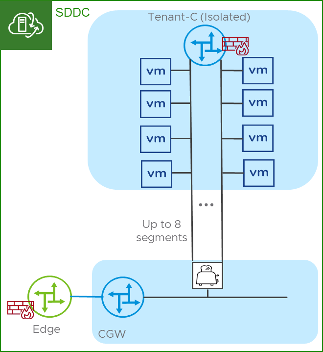
Figure 3 – CMA in a default gateway configuration
Some additional considerations beyond the topology used include the following topics.
- When using a customer managed appliance (CMA) it is the customer’s responsibility to size and possibly license the virtual machine and appliance to support their specific use case. As this will be vendor/appliance specific please refer to their specific documentation. vSphere options like CPU and memory reservations may be desirable and we encourage customers to work with their CMA vendor for specific settings.
- CMA placement in the SDDC is important as the possibility of traffic hairpinning through the CMA is likely and will have an impact on the host’s network performance. In a hairpinning scenario, traffic will traverse the host’s NIC twice, in effect, doubling the PPS the host experiences.
- Figure 4 depicts the logical topology where an isolated segment has guests that span multiple hosts and illustrates the traffic flow from a guest to the CMA and back to the routed infrastructure.
- Figure 5 depicts the physical topology and illustrates the path in more detail reflecting the ingress and egress of traffic through the CMA and the host’s physical NIC.
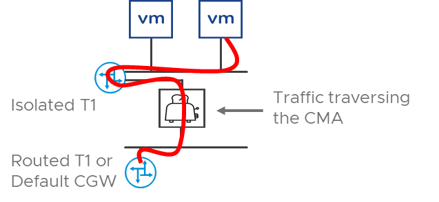
Figure 4 – Logical Topology of CMA traffic flow
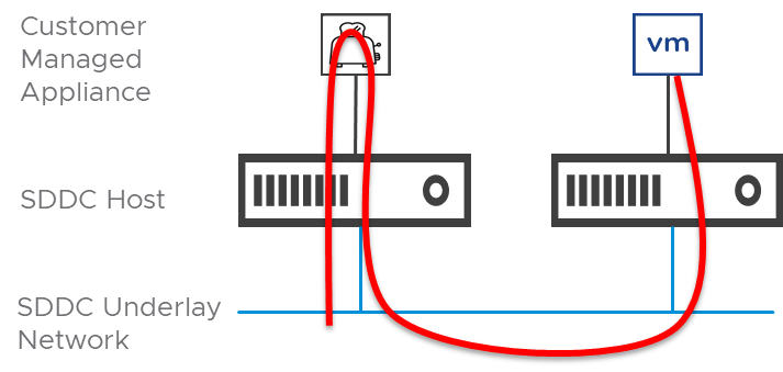
Figure 5 - Traffic hairpinning from a physical view
- CMA high availability using First Hop Redundancy Protocols (FHRPs) isn’t an option due to the Virtual Distributed Switch (VDS) not allow MAC learning. Other redundancy like a heartbeat dead-net segment, or heartbeat across the data plane interfaces should be considered. If a dedicated HA segment is used, note that it deducts from the 9 total vNICs a guest VM supports. It’s also important to note that VMC on AWS does not support VLAN/segment trunking into a guest (802.1q or other similar technologies) as well as vSphere Fault Tolerance (FT). In the event no other redundancy is available, the customer may consider relying on vSphere HA for the CMA. vSphere anti-affinity policies may be beneficial in this scenario.
Implementation
The specific implementation of the additional T1s to utilize this capability can be found in the NSX Manager User Interface. The configuration steps for the recommended deployment from a high level would include the following tasks.
- Create an Isolated T1. Note, once a T1 is configured as Routed, NATted or Isolated its type may not be changed.
- Create segments and attach them the Isolated T1.
- Deploy CMA and attach it to a segment connected to the Isolated T1 this will be the “inside” interface.
- Attach the CMA to a segment connected to either a Routed T1 or the Default CGW. This will be the “outside” interface.”
- Configure a static default IPv4 route (0.0.0.0/0) on the Isolated T1 using the IP address of the “inside” interface as the next hop.
- Configure NAT, routing and any other appropriate policy on the CMA to meet the customer’s requirements.
Monitoring and Supportability
When using a customer managed appliance (CMA) in any capacity, the customer is responsible for monitoring all performance metrics and availability. This monitoring also includes the ESX host where the CMA is running from a memory, CPU, network uplink and availability. Special attention should be taken to understand the packet rates and associated drops that may be experienced due to the volume of the traffic and potential hairpinning.
With the two topologies covered in this document, there are some clear distinctions between observability between them which in turn has an impact on supportability. In the recommended topology, VMware will have observability over the segments and the Isolated T1 where traffic can be observed from the originating guest, across the segment, into the Isolated T1, out of the Isolated T1 to the transit segment and on the vNIC into the CMA ,the “inside” interface. If traffic meets the forwarding requirements in the CMA, VMware support will be able to resume observability on the vNIC of the CMA, the ”outside” interface and into the routed network. This means the only “blind spot” is what happens to the traffic once it enters the CMA. Figure 6 depicts the observability points in the recommended topology.
Figure 6 – Observability in the recommended topology
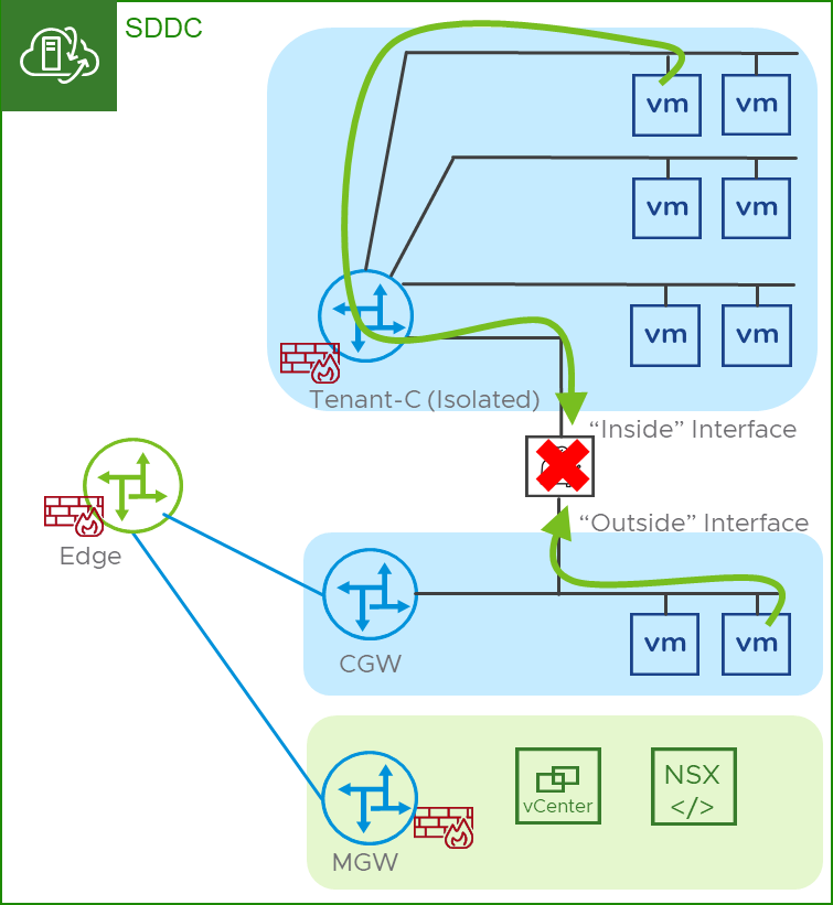
In Figure 7 we can see two examples of traceflow operations with a CMA inline. One traceflow is from a guest in the isolated segment to a guest in the default CGW segment. The 2nd traceflow is from the guest in the default CGW segment to the guest in the isolated segment. Both traceflows are unable to show the complete end-to-end path because the CMA is inline.
Figure 7 – Traceflow with a CMA inline
In the CMA as a default gateway model, the VMware support observability is greatly reduced as the T1 is no longer in the path. VMware will be able to see traffic on the vNIC into the CMA ,the “inside” interface. If traffic meets the forwarding requirements in the CMA, VMware support will be able to resume observability on the vNIC of the CMA, the ”outside” interface and into the routed network.
It’s important to note that the observability on the vNICs is facilitated using the port mirroring function of NSX which is intended for limited use in troubleshooting scenarios. Packet captures from the port mirror will need to be forwarded to a destination reachable by the SDDC’s management CIDR for analysis using a packet analysis tool. This is time consuming and labor intensive.
Additionally, the traceflow troubleshooting tool introduced in VMC 1.16 does not operate through CMAs.
With any CMA deployment, the customer is responsible for ensuring their appliance will support the VMC SDDC versions after any upgrades. VMware will not do any compatibility testing for CMAs.
Summary
The capability to configure static routes on customer created T1s introduced in VMC on AWS 1.18 opens new networking topology options. Customers who plan to use this for the intended use cases need to take multiple considerations into account before deploying any customer managed appliances (CMA). These considerations may have performance and operational impacts on workloads using the CMA that VMware may be limited in providing support for.
Author and Contributors
Author: Ron Fuller