
Anatomy of OCI networking and its building blocks
Introduction
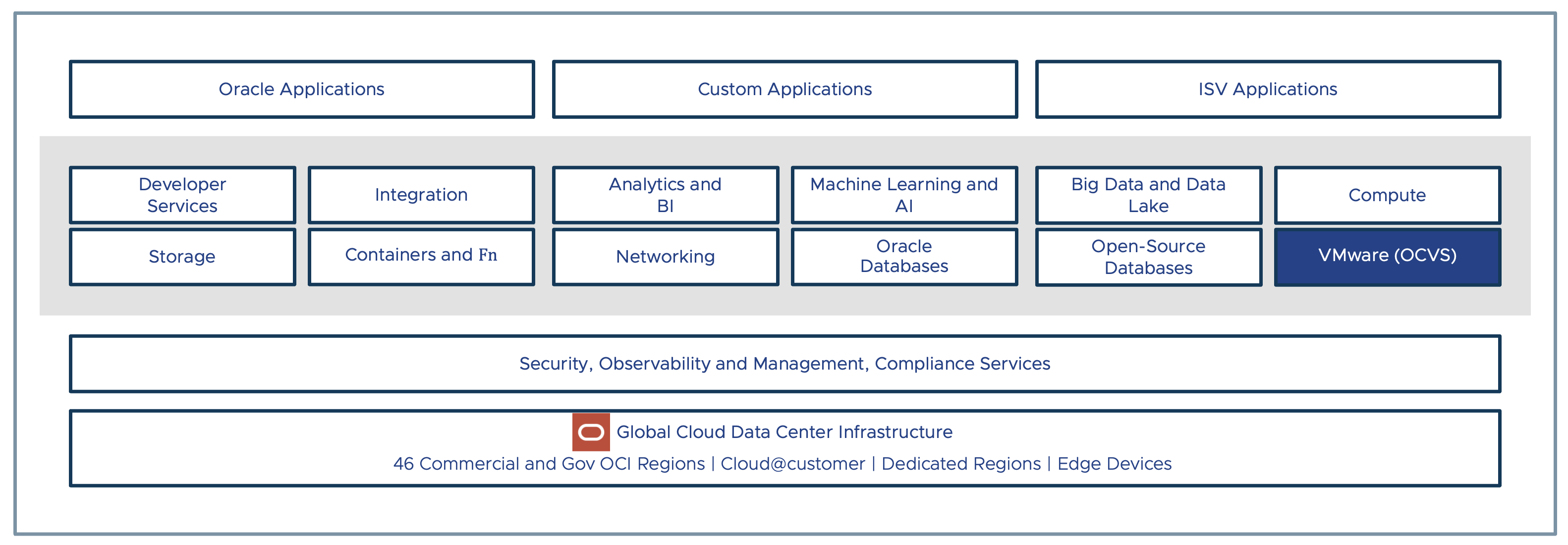
Oracle Cloud VMware Solution (OCVS) is a native OCI service that allows you to build VMware Software Defined Datacenter (SDDC) in Oracle Cloud Infrastructure (OCI). OCVS is a native OCI service that leverages core OCI infrastructure to deliver full-fidelity VMware service in the cloud. OCVS networking is just an extension of the native OCI networking services and does not use any out-of-the-box networking solution to deliver VMware service in Oracle Cloud.
In this part, we will deep dive into OCI networking to understand more about networking services and their building blocks. This will lay the foundation to learn OCVS networking in the upcoming chapters
Key takeaways from this chapter-
- OCI topology
- OCI networking topology
- VCN
- OCI gateways
- Routing and Firewall services
- OCI Networking Scenarios
Scope of the Document
This topic requires a basic understanding of networking concepts such as LAN, WAN, VPN, and IP addressing. Also, a basic understanding of cloud concepts such as cloud regions, public cloud infrastructure, availability and resiliency is an added advantage.
Primary audience
- Cloud Administrators
- System Administrators
- Cloud Architects
OCI Topology
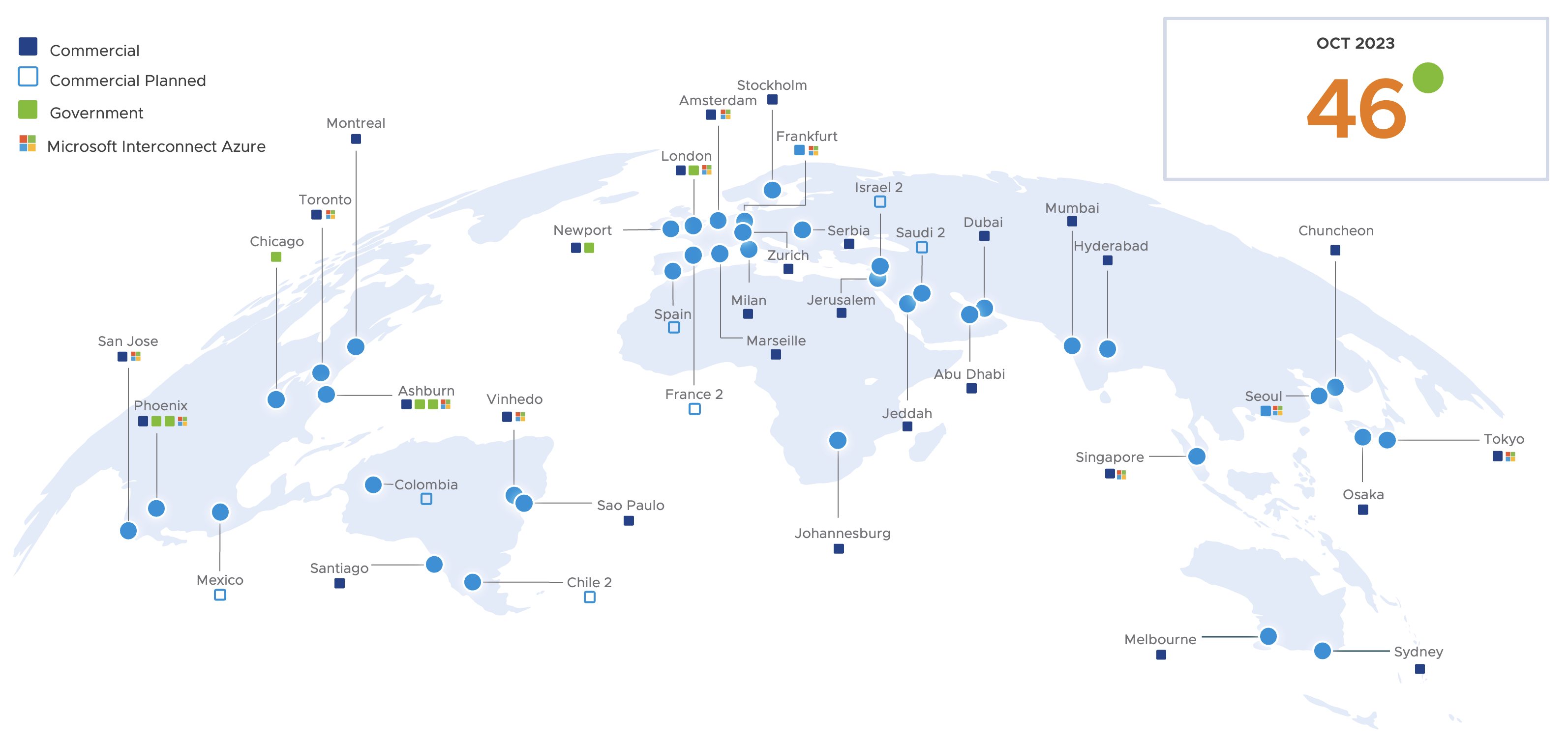
Oracle Cloud Infrastructure (OCI) is a comprehensive public cloud infrastructure offered by Oracle to deliver a variety of cloud services, including Infrastructure as a Service (IaaS), Platform as a Service (PaaS), and Software as a Service (SaaS). This is backed by a highly resilient, secure, and scalable infrastructure. The OCI infrastructure is available globally with 46 public cloud regions.
Let us look at OCI topology to understand various constructs such as regions, availability domains, fault domains, tenants, and compartments. This will help you understand the basics of Oracle Cloud Infrastructure and will be helpful when we learn more about OCI networking.
OCI Region
Oracle Cloud Infrastructure (OCI) is hosted in a geographical location and that is called a region. There are currently 46 commercially available regions. These are the public cloud regions that anyone can subscribe to. Other than public cloud regions there are other type of regions also available such as GovCloud, Dedicated, and cloud@customer regions.
- GovCloud regions, exclusively available to US Federal Government to host their services and workloads on OCI.
- The dedicated regions provisions dedicated OCI resources isolated with other OCI tenants.
- cloud@customer, allows customers to build OCI region in their own datacenter for improved privacy and security.
Availability Domains
An availability domain can easily be described as one or more datacenters located in a OCI regions. The number of availability domain varies region to region but typically there are either 1 or 3 availability domains in one region.
Fault Domains
A fault domain is a grouping of hardware and infrastructure within an availability domain. Each availability domain contains three fault domains. Fault domains provides anti-affinity of your cloud resources thus allowing you to you distribute your instances for resiliency purpose. A hardware failure in one fault domain does not affect resources in other fault domains.
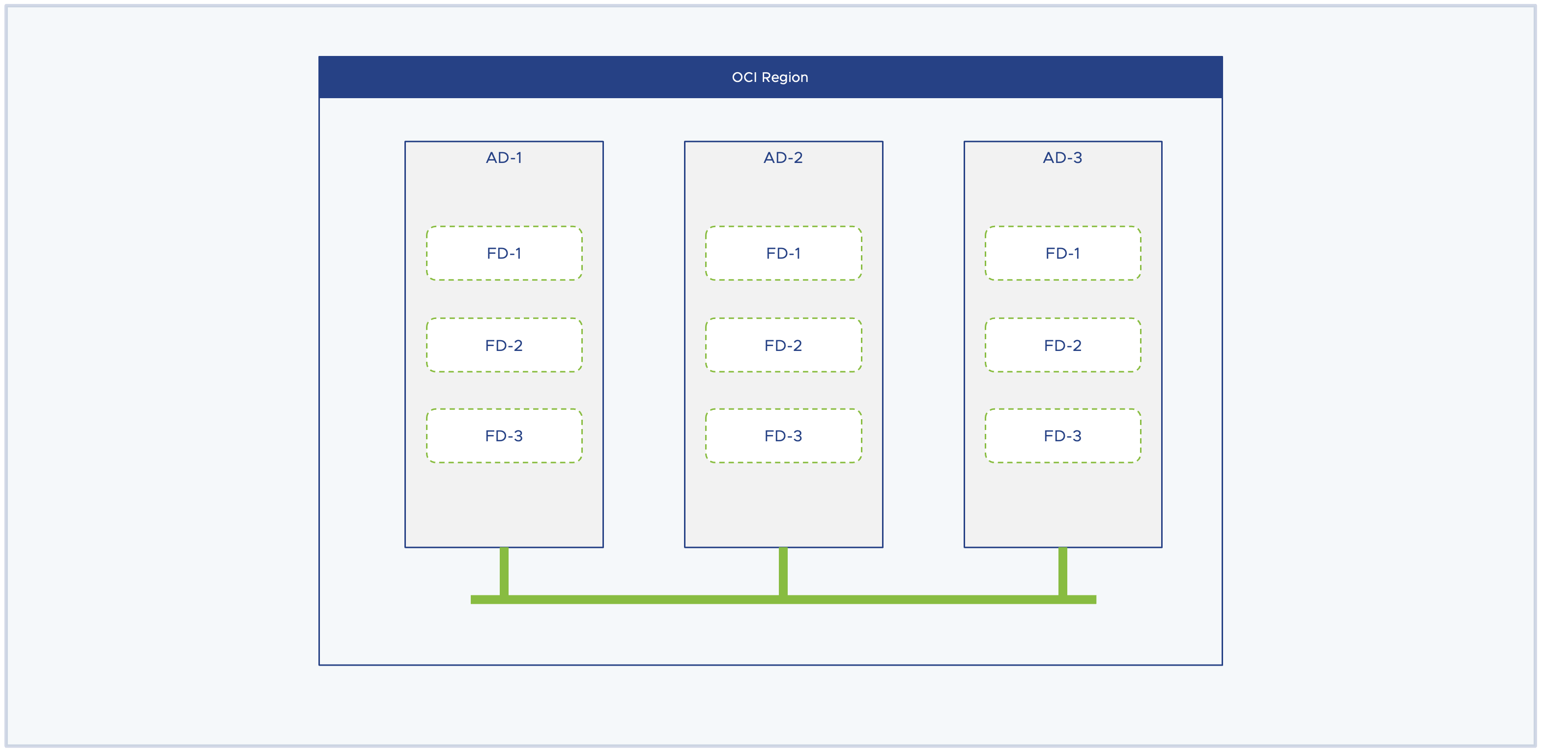
In the context of Oracle Cloud VMware Solution (OCVS), the deployment workflow provision the entire SDDC in a single availability domain but distribute ESXi instances equally across the three fault domains thus eliminating a possibility of single point of failure.
OCI Networking
Today, enterprise workloads are delivering mission-critical services across the verticals. These workloads demand scalability, agility, and performance in the most secure manner from an underlying infrastructure. This stands true irrespective of the type of infrastructure such as on-premises, private cloud, or public cloud infrastructure. Oracle Cloud Infrastructure is rightly architected to deliver the exact same demands that I have outlined earlier. Let us look at a high-level overview of OCI networking constructs and understand how it is offering a scalable, agile, and high-performance networking stack to deliver mission-critical workloads in OCI.
Core Networking Architecture
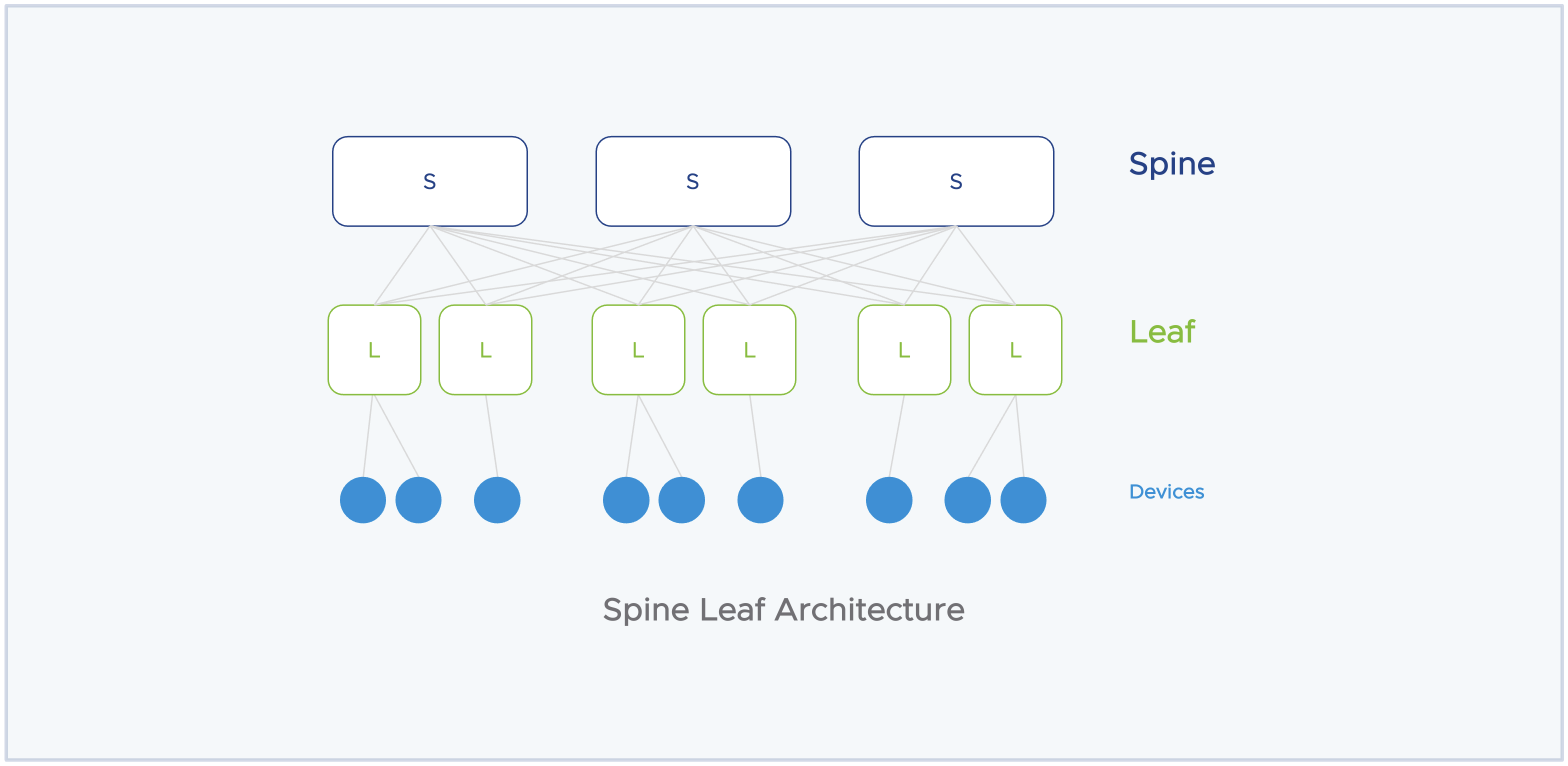
OCI offers a robust high-performance networking infrastructure with a zero-trust model. The backend OCI network infrastructure is a 2-tier network architecture also known as spine-leaf architecture. In a typical, 3-tier architecture you have a core layer, aggregator layer, and access layer. This architecture works well when you want to scale up your resources but often end up with a ‘noisy neighbor’ problem or a network collision problem in a multi-tenant environment.
In contrast to 3-tier networking architecture, the 2-tier network architecture is a flattened network topology with only 2 layers to it, spine and leaf. The spine layer act is the backbone of the network infrastructure, and all the leaf switches connect to all the spine switches in the topology. All the servers, devices, and endpoints connect to the leaf switch, and through the leaf switch it connects to other nodes in the environment. This architecture avoids the situation of network collision and offers better network performance compared to the 3-tier network architecture thus offering a better prospect of hosting stateful applications in a public cloud, multi-tenant infrastructure.
Another backend piece in the OCI networking is the off-box data processing unit (DPU) control plane to offload control plane tasks from the actual resource. This offers 100% of compute, network, and storage resources to customer workloads or services. Lastly, the OCI rack design incorporates remote direct memory access (RDMA) over converged ethernet backplane into OCI bare metal nodes to deliver vertically scaled-up clustered networking with an improved networking performance.
Combining all these key design implementations allows OCI to deliver a robust, scalable, and high-performing networking infrastructure for running mission-critical workloads.
OCI Networking Building Block
Let us learn about some of the OCI building blocks that together deliver networking services in OCI. In this section, we will learn about –
- Virtual Cloud Network
- Subnets
- Route Table
- Security List and NSG
- Gateways
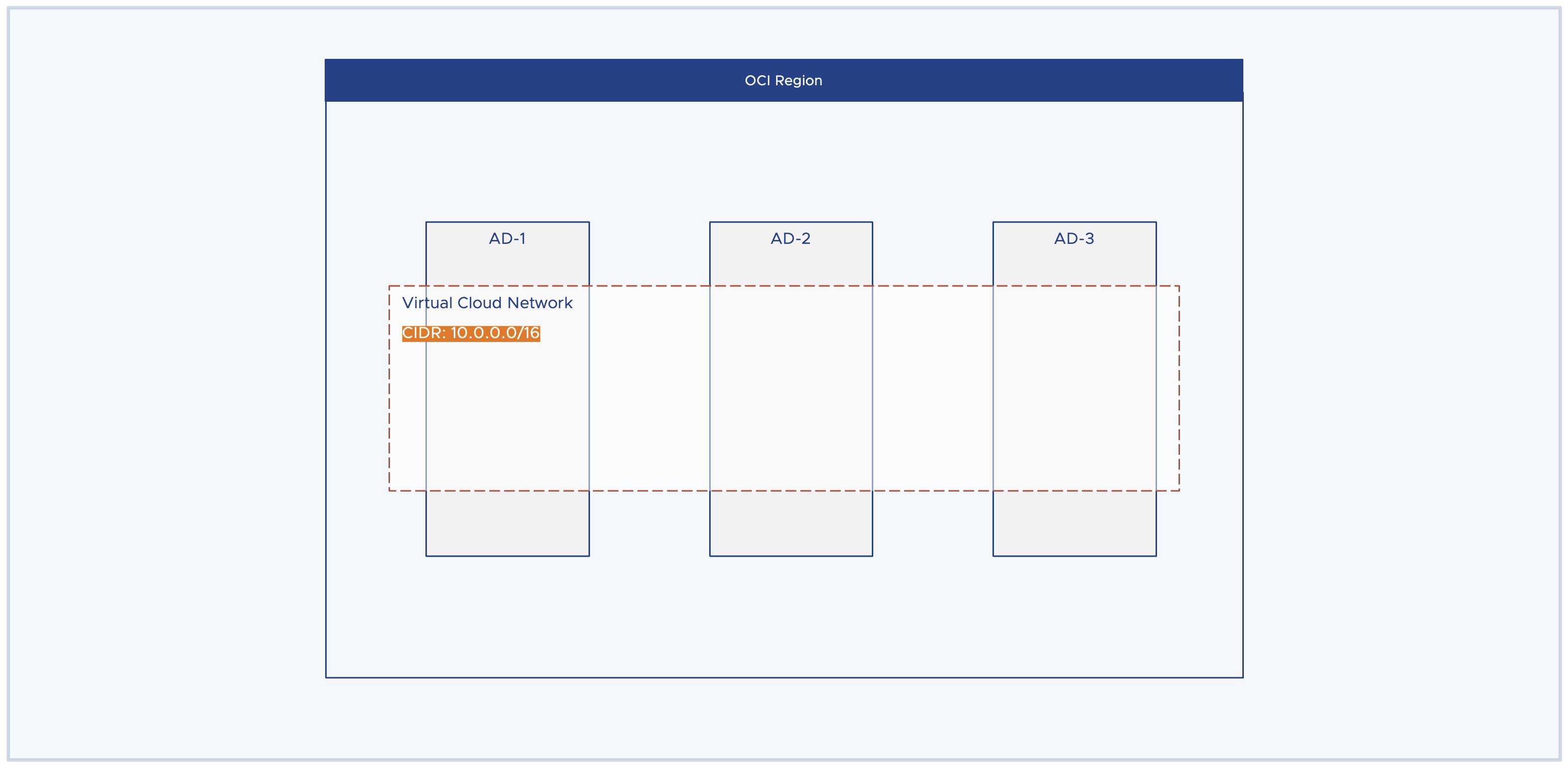
Virtual Cloud Network (VCN)
The Virtual Cloud Network (VCN) is a logical networking construct. It is a private network that you set up in the OCI region. The idea of VCN is to create a large enough private network that meets your capacity demands and eventually, you should be able to carve out different subnets from this large virtual private network to meet the workload demands. VCN is a region-wide construct spanning all the availability domains in a region. Key points to note before creating a VCN.
- You must consider the sizing requirements before provisioning a VCN.
- VCN allows you to have multiple CIDR blocks but these CIDR blocks should not overlap with other VCN’s CIDR block. Simply avoid the situation of IP conflict.
- The allowable VCN size range is /16 to /30. Example: 10.0.0.0/16. The idea here is to choose an IP prefix that meets the IP address capacity demands. The prefix /16 gives you 65,534 usable IP addresses and with /24 it gives 254 IP addresses.
- Oracle recommends RFC 1918 for provisioning private IP ranges. Except /12 and /8 because OCI only supports ranges from /16 to /30.
- VCN supports both IPv4 and IPv6 addressing.
Subnets
Once you have large enough CIDR provided by VCN you can carve out multiple subnets from it, it is essentially a subdivision of VCN. Each subnet contains a unique contiguous IP range that do not overlap with other subnets in the same VCN but are subset of VCN CIDR range. For example, If the VCN CIDR range is 10.0.0.0/16 then subnet’s CIDR range can be 10.0.0.0/24, 10.0.1.0/24, or 10.0.8.0/21. The key here is, that the subnet CIDR should not overlap with other subnet’s CIDR and it should be a subset of 10.0.0.0/16, which is the VCN CIDR range.
A subnet contains virtual network interface cards which attach to an instance. All instances or VNICs attached to the same subnet use the same route table, security lists, and DHCP options.
In OCI, there are two types of subnets –
Private Subnet, VNICs in a private subnet cannot have a public IPv4 address, and internet access via IPv6 is prohibited. The instances part of the private subnet can initiate the connection to the internet (Outbound) but protects instances from inbound connection from the internet.
Public Subnet, VNICs in a public subnet can have a public IPv4 address, and internet communication with IPv6 interface is allowed. Instances in this subnet are allowed to have inbound as well as outbound network connections with the internet.
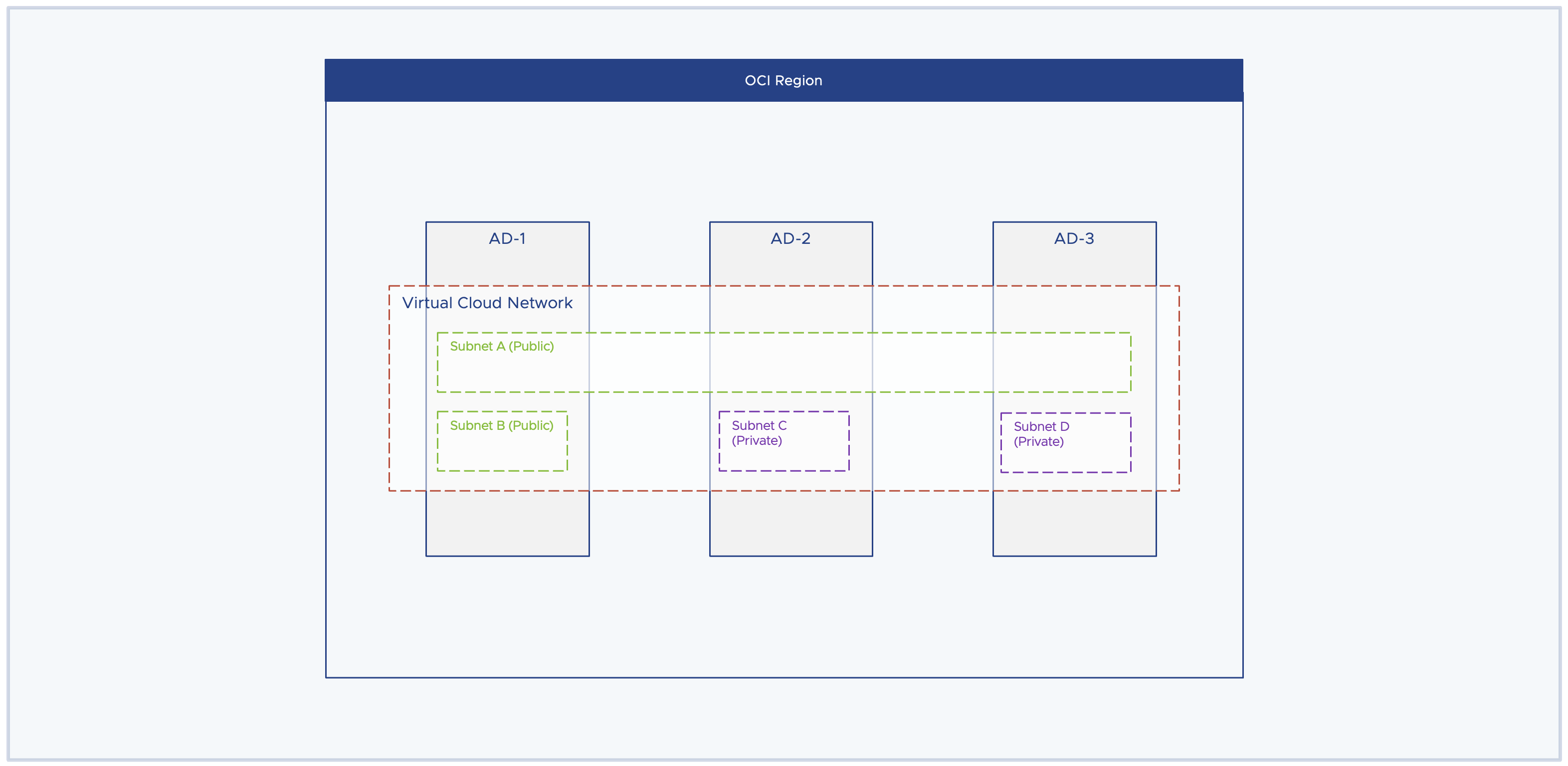
Both public and private networks are AD-specific or region-wide subnets. The AD-specific subnets mean that resources need to reside in a specific availability domain and resources outside of this availability domain do not have access to this subnet and its resources. Whereas the region-wide subnet means that resources across the region can have access to the subnet resources irrespective of which availability domain they belong to. Region-wide subnet offers more flexibility in overall network design.
In the below diagram, Subnet A is a region-wide subnet and Subnet B/C/D are AD-specific subnets only. As stated earlier, both public and private subnets can be either AD-specific or region-wide subnets.
Each subnet has 3 additional components attached to it –
- Route Table
- Security List
- DHCP Option
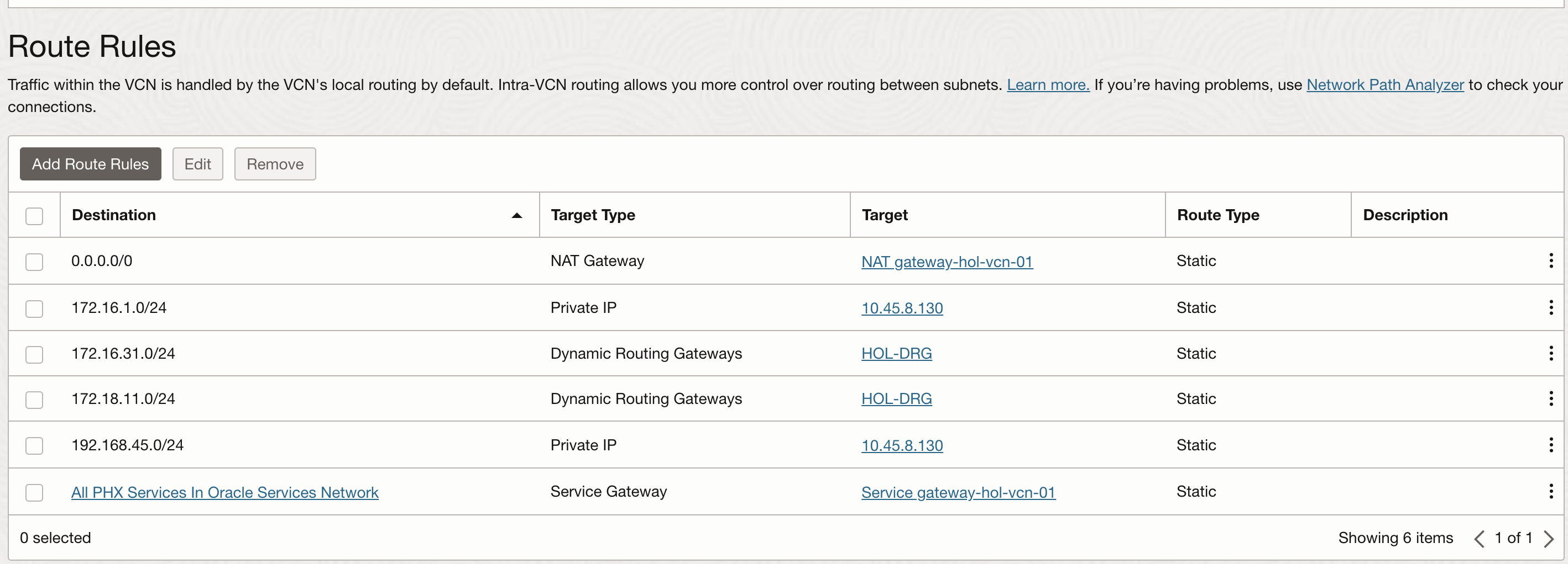
Route Table
The route table contains route rules that specify the destination CIDR block and the next hop to reach there. Each VCN has a default route table and it allows traffic to go outside of VCN. You can create a new route table and attach them to a subnet. While provisioning a subnet if the route table is not specified then the VCN default route table is attached to the subnet.
Below is an example of how does route rules are specified in a route table.
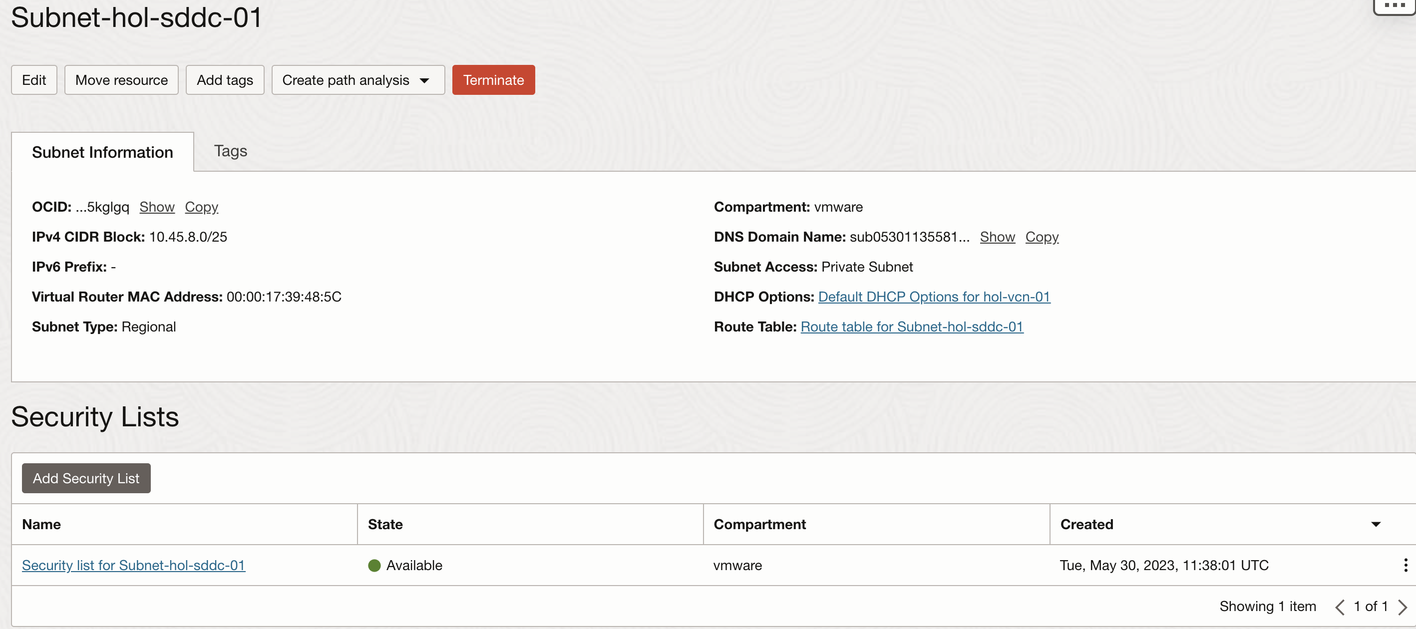
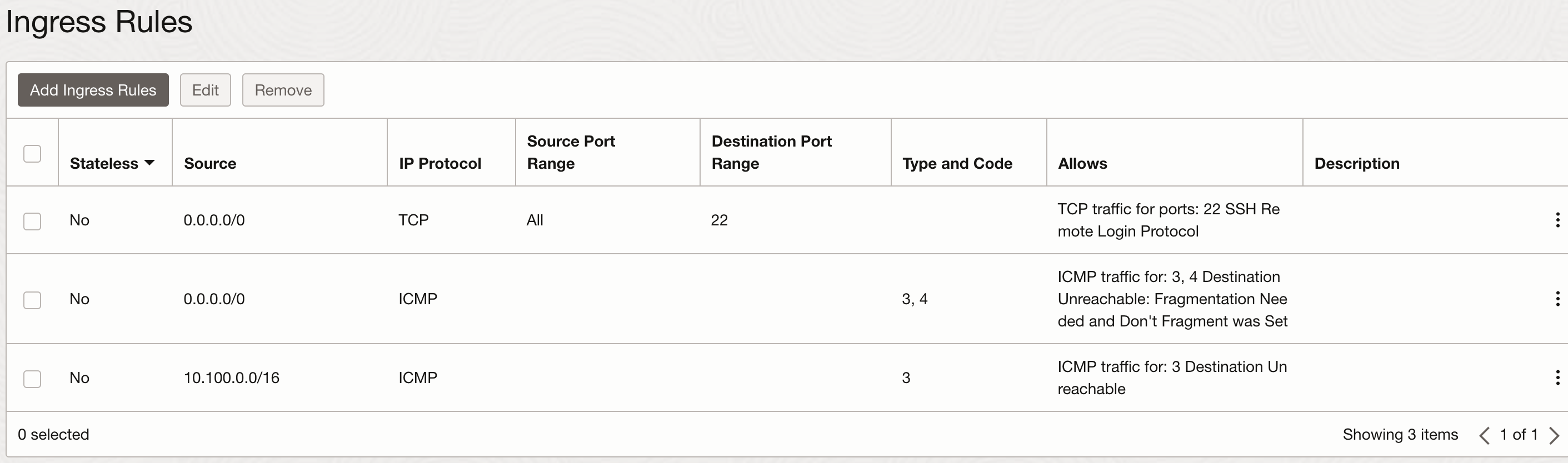
Security List
Security List is a virtual firewall which defines security rules to specify the type of traffic allowed in an out of the instance. Each security list is enforced at the VNIC level, but you can configure security list at the subnet level which allows you to define firewall rule for all the VNICs in the given subnet. Each security list can have multiple security rules and each subnet can have multiple security list attached to it.
Below is an example of security list attached to a subnet and list of security rule specified.
Gateways
There are different types of gateways you can create in a VCN. The type of gateway depends upon the specific use case.
Internet Gateway, Optional router that you can create and attach to a public subnet. All the VNICs having a public IPv4 address can use this gateway to establish a two-way (Inbound and Outbound) connection to the internet.
NAT Gateway, Optional router that you can create and attach to a private subnet. This gateway allows instances to establish an outbound connection with the Internet but protects instances from inbound connections from the Internet.
Dynamic Routing Gateway (DRG), Dynamic Routing Gateway provides a path for private network traffic between VCN and on-premises environment. You can use DRG with IPSec VPN or OCI FastConnect service to establish network connectivity between these two environments.
Service Gateway, Provides a path for private network traffic between VCN and Oracle Service Network. If you are using a service gateway to access any service in Oracle Service Network such as the autonomous database then the traffic does not go through the internet and does not require a public IPv4 address.
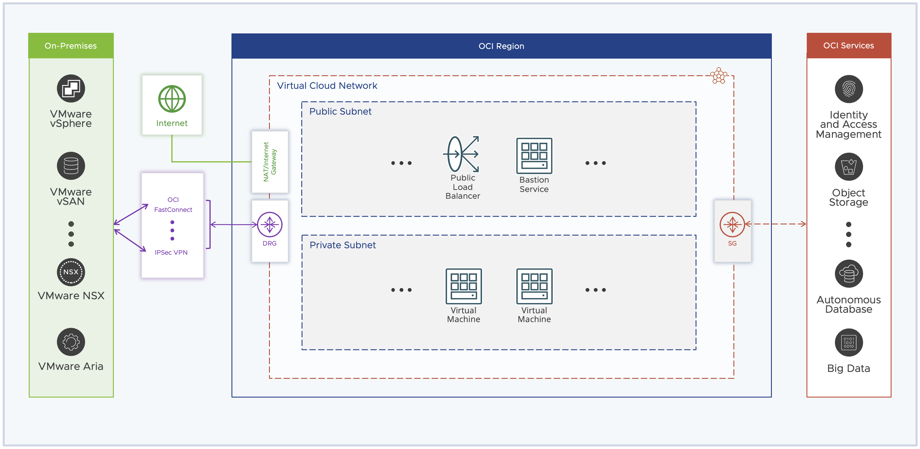
Below is a complete picture of what OCI networking looks like from a high level.
Conclusion
In this article, we have learnt about OCI networking and its building blocks. These concepts are very important and will play a critical role to understand how OCVS networking is designed in OCI.